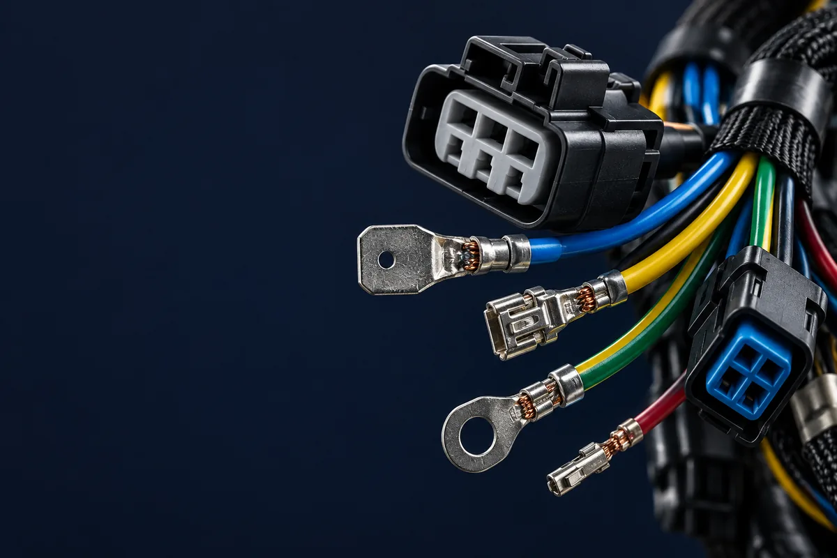
Direct answer: Diagnose a wire harness failure by locating the affected circuit, preserving the failed termination, and separating an open circuit, unwanted short, excessive series resistance or insulation leakage. Compare the suspect path with the drawing and a known-good assembly, then correlate electrical measurements with crimp condition, connector retention, routing and environmental exposure before assigning a root cause.
Wire harness defects can cause electrical faults, recalls, and service disruption. This guide breaks down seven common failure modes and prevention strategies that help control manufacturing and field risks.
1. The True Cost of Wire Harness Failures
Wire harness failures can trigger safety recalls, production shutdowns, and field failures. The financial exposure depends on the affected population, fault severity, and corrective action required.
Potential Recall Risks
The following are illustrative harness fault scenarios, not documented recall case studies:
| Harness application | Affected scope | Root Cause |
|---|---|---|
| A/C harness | Depends on affected production lots | Fire risk from wiring defect |
| SUV Airbag Harness | Depends on affected production lots | Faulty airbag wiring connections |
| Commercial Truck Engine Harness | Depends on affected production lots | Improperly routed harness causing shutdowns |
| EV Rearview Camera Harness | Depends on affected production lots | Vibration damage to camera wiring |
| Coaxial Cable Connector Defect | Depends on affected production lots | Faulty coaxial connectors |
Understanding these seven failure modes helps identify appropriate controls. Let's examine each one with illustrative examples and prevention strategies.
2. Failure #1: Bad Crimps (The Silent Killer)
Crimp failures are a common wire harness fault. A crimp may look acceptable on the outside while hiding internal voids, insufficient compression, or wire strand damage that can fail under stress.
Types of Crimp Failures
Under-Crimping
- • Insufficient compression force
- • Wire pulls out under tension
- • High-resistance connection
- • Intermittent contact under vibration
Over-Crimping
- • Excessive force crushes wire strands
- • Reduced current-carrying capacity
- • Brittle connection prone to fracture
- • Insulation damage at crimp zone
Crimp Quality: Manual vs Automated
| Method | Defect Risk | Detection Method | Best For |
|---|---|---|---|
| Hand crimping tools | Depends on tool setup and operator control | Visual + pull test | Prototypes and approved production work |
| Semi-automatic machines | Depends on setup and monitoring | Crimp height monitoring | Low-medium volume |
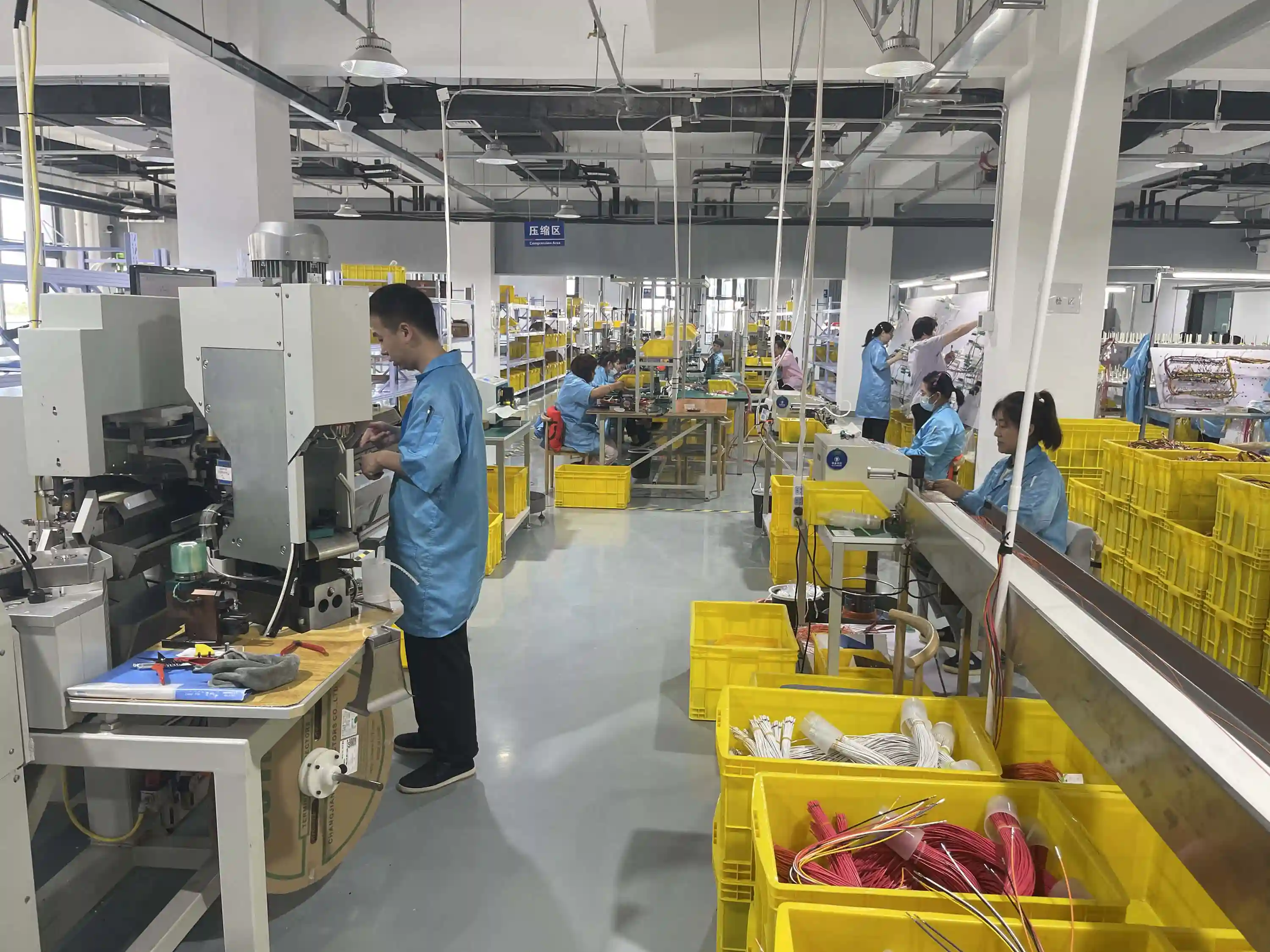
| Fully automated + CFM | Depends on process capability and validation | Crimp force monitoring + cross-section | High volume production |
Hidden Defect: Internal Voids
A crimp can pass visual inspection and even basic pull testing while containing internal voids—air pockets between wire strands and the terminal barrel. These voids create moisture ingress pathways that lead to corrosion and eventual failure. Cross-section analysis (micrograph) can reveal internal voids at the section examined.
For a complete overview of testing methodologies, see our wire harness quality testing guide .
3. Failure #2: Chafing & Abrasion Damage
Chafing occurs when a wire harness rubs against a sharp edge, bracket, or adjacent component over time. The insulation gradually wears away, exposing the conductor. The result: short circuits, ground faults, or even fires.
Frayed conductors from chafing can cause shorts as a vehicle ages. The insidious nature of chafing is that it's a slow-degradation failure—the harness passes all factory tests but fails months or years later in the field.
Prevention Strategies
- Routing verification: Use 3D CAD routing simulation to identify potential contact points before production
- Protective sleeving: Apply convoluted tubing, braided sleeving, or split loom at all contact zones
- Edge protection: Install grommets at every metal panel pass-through
- Clip spacing: Set clip spacing from the routing, harness mass, and validated vibration requirements
- Service loop management: Ensure proper strain relief so harness doesn't shift into contact with edges
Our cable assembly design guide covers DFM principles that prevent chafing at the design stage.
4. Failure #3: Corrosion & Moisture Ingress
Moisture at copper conductors or terminal contacts can promote corrosion, increasing resistance and potentially causing open circuits. Marine and outdoor applications need protection suited to their exposure.
Corrosion Protection Comparison
| Protection Method | Cost Impact | Effectiveness | Best Application |
|---|---|---|---|
| Tinned copper conductors | Depends on material and process | Excellent | Corrosive environments, subject to compatibility review |
| Sealed connectors with an application-appropriate ingress rating | Depends on material and process | Excellent | Underhood, marine, outdoor |
| Dielectric grease on terminals | Depends on material and process | Good | Contacts approved for the specified lubricant |
| Adhesive-lined heat shrink | Depends on material and process | Excellent | Splice and transition points |
| Conformal coating | Depends on material and process | Excellent | PCB/harness interfaces |
For details on material selection for harsh environments, read our wiring harness materials guide .
5. Failure #4: Vibration Fatigue
Vibration-induced failures are particularly dangerous because they typically manifest as intermittent problems that are extremely difficult to diagnose. When a wire harness is subjected to continuous mechanical vibration—common in automotive, industrial, and industrial machinery—individual conductors can fracture due to metal fatigue even when the harness appears physically intact.
Vibration can cause relative motion and fretting between strands or shield elements. Inspect for internal wear and fatigue damage when investigating intermittent faults, even if the outer jacket appears intact.
Vibration Failure Prevention
Design Controls
- • Route harness away from vibration sources
- • Use flexible wire types (stranded, not solid)
- • Design service loops at connection points
- • Specify vibration-rated connectors
Mounting Controls
- • Clamp harness at regular intervals
- • Use vibration-dampening clip mounts
- • Avoid cantilevered harness segments
- • Apply strain relief at all connectors
Inadequate mounting can allow vibration to damage conductors and terminations. Select the vibration test method and severity from the applicable vehicle specification and connector qualification requirements.
6. Failure #5: Thermal Degradation
Excessive heat can accelerate insulation aging. Continuous and short-term temperature limits depend on the specific wire construction and exposure duration. Over time, thermally degraded insulation can become brittle, crack, and expose conductors.
Insulation Temperature Ratings
| Insulation Type | Continuous Temperature Limit | Common Applications |
|---|---|---|
| PVC | Check the specific wire rating | General purpose, interior |
| XLPE (Cross-linked PE) | Check the specific wire rating | Automotive, industrial |
| Silicone | Check the specific wire rating | Engine bay, exhaust proximity |
| PTFE (Teflon) | Check the specific wire rating | industrial, extreme environments |
Thermal Exposure Near Accessories
A harness routed near a hot accessory can suffer insulation damage. Review the measured temperature profile, clearance, insulation rating, and any thermal shielding before choosing corrective action.
For EV applications where high-voltage harnesses face unique thermal challenges, see our EV high-voltage wire harness guide .
7. Failure #6: Connector & Terminal Failures
Connector fit issues can cause intermittent wire harness faults. Problems include incomplete terminal insertion, incorrect mating, inadequate clearance from moving parts, and tin whisker growth.
Common Connector Failure Modes
- Backed-out terminals: Terminal not fully seated in connector housing, loses contact under vibration
- Tin whiskers: Microscopic metallic growths on tin-plated terminals that cause shorts
- Incorrect mating force: Connector too loose or too tight, causing either intermittent contact or housing damage
- Seal failure: O-ring or grommet seal degradation allowing moisture ingress
- Wrong connector selected: Using a non-vibration-rated connector in a high-vibration application
Prevention tip: Implement a “click audit” on the assembly line—train operators to verify the audible or tactile click confirmation when mating connectors. For automated assembly, use insertion force monitoring to verify each terminal is fully seated.
8. Failure #7: Manufacturing & Assembly Defects
Beyond crimp quality, several manufacturing process errors contribute to wire harness failures. According to Carr Manufacturing, assembly errors can be reduced through appropriate process controls.
| Defect Type | Root Cause | Prevention |
|---|---|---|
| Wrong wire gauge | BOM error or operator mistake | Barcode scanning at wire prep |
| Mis-routed wires | Complex assembly board layout | Light-guided assembly systems |
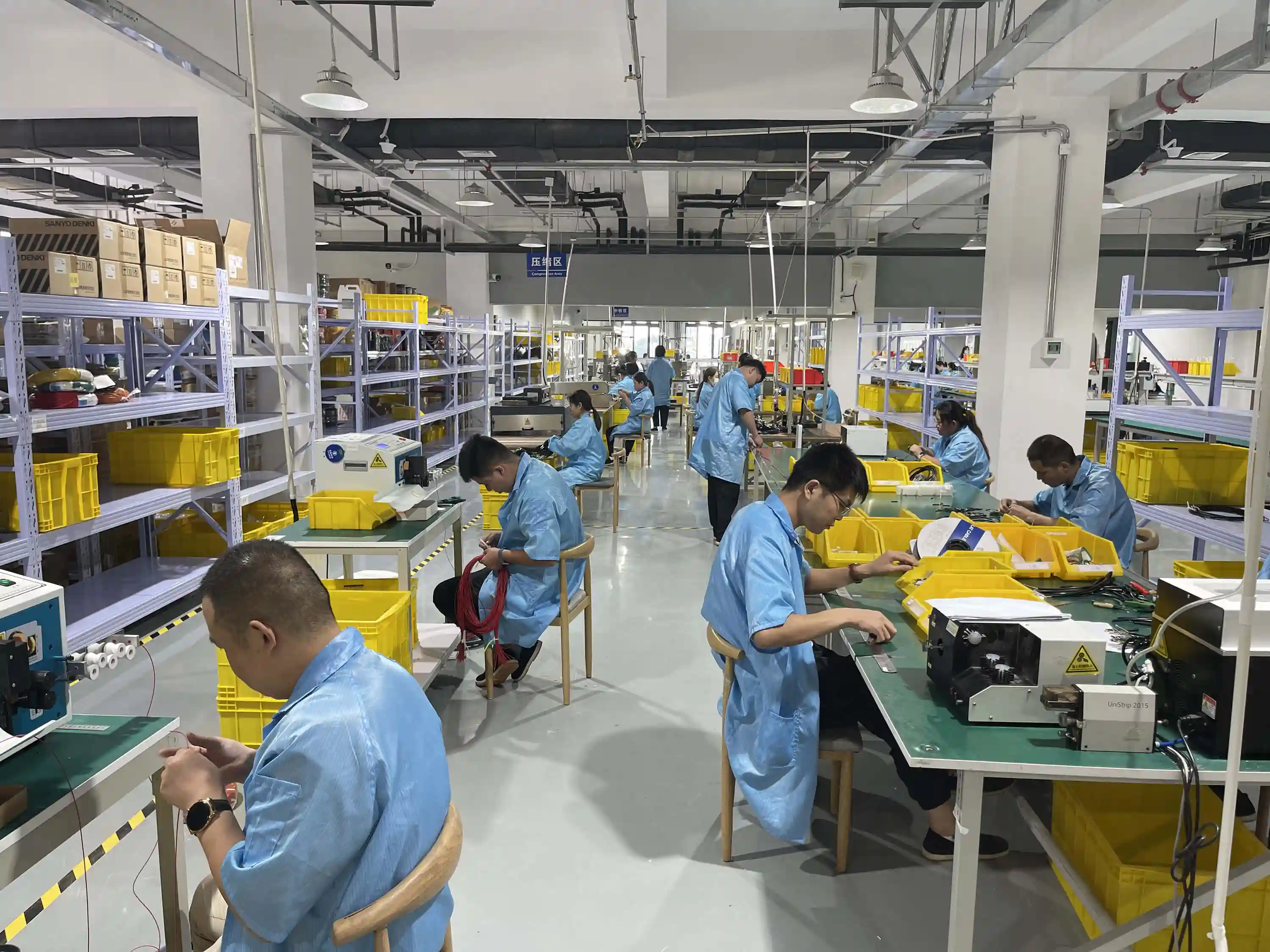
| Insulation nicks | Improper strip length setup | Automated strip-length verification |
| Wrong wire color | Inventory mix-up | Color verification at each station |
| Missing components | Skipped assembly step | Poka-yoke fixtures, checklist systems |
| Incorrect torque | Operator error, uncalibrated tools | Torque-controlled tools with logging |
Wire color confusion can contribute to misdiagnosed field faults. For global manufacturing, understanding color code standards is critical—see our Chinese vs international wire color code guide .
9. Defect Prevention Framework
Design review, process controls, testing, and feedback from field failures can help reduce wire harness defects. The following framework groups these controls by lifecycle stage.
Four Pillars of Prevention
Design Prevention
- • 3D CAD routing simulation
- • DFMEA (Design Failure Mode Analysis)
- • Component derating guidelines
- • Environmental specification review
Process Prevention
- • Automated crimping with CFM
- • Poka-yoke (error-proofing) fixtures
- • Light-guided assembly systems
- • SPC (Statistical Process Control)
Testing Prevention
- • 100% continuity testing
- • Hipot (dielectric) testing
- • Pull-force testing to the applicable terminal and assembly requirements
- • Environmental stress screening
Lifecycle Prevention
- • Preventive maintenance programs
- • Field failure data collection
- • Warranty claim root cause analysis
- • Continuous improvement (PDCA cycle)
For information on certifications relevant to these quality practices, read our top 5 wire harness certifications guide .
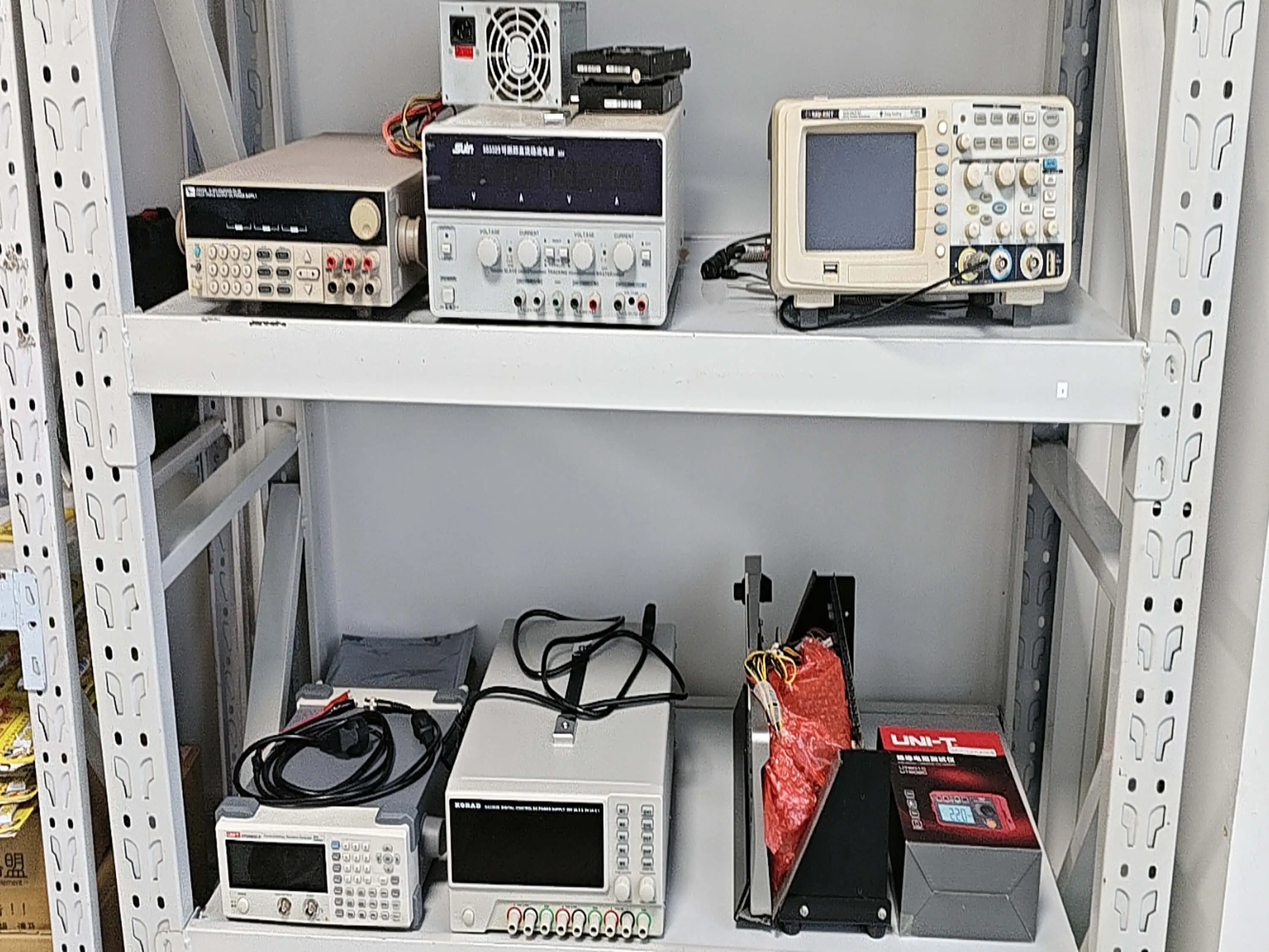
Quantitative Checks for Intermittent and Overheating Failures
1. Subtract the expected wire contribution. Belden 9918 is an 18 AWG stranded tinned-copper wire with nominal conductor resistance of 7.15 Ω/1,000 ft. A hypothetical circuit with a 10 ft outbound wire and a 10 ft return therefore contributes 0.143 Ω before connections. At an assumed 5 A load, calculated wire drop is 0.715 V. Reference values: use the specific model's datasheet and measurement temperature. Measure separate path segments before blaming a connector for resistance attributable to wire length.
2. Translate excess resistance into local heating. If a suspect joint adds a measured 0.050 Ω at an assumed 5 A, Ohm's law gives an additional 0.250 V drop and 1.25 W of localized dissipation: V = IR and P = I²R. This is a worked calculation, not a field measurement or acceptance limit. Record the actual current, voltage drop and temperature together; a continuity beep cannot quantify this loss. Repeat using the same load and sense-point locations when comparing the failed and known-good assemblies.
3. Check the terminal suffix when vibration causes intermittency. JST identifies SXH-001T-P0.6N as a low-insertion-force XH contact and warns that it is less resistant to vibration. Reference information: verify the exact part's datasheet. A matching housing and successful static continuity test do not establish identical vibration behavior after a contact substitution. Preserve the terminal packaging or lot record and compare the approved BOM suffix before ordering replacement parts. Source: JST XH catalog, contact note on page 3.
10. Root Cause Analysis: The 5-Why Method for Wire Harness Failures
When a wire harness fails in the field, identifying the true root cause—not just the symptom—is critical to preventing recurrence. The 5-Why method is a simple but powerful technique widely used in automotive and industrial quality systems.
Hypothetical 5-Why Example: Intermittent Engine Stall
Problem: Engine stalls intermittently. → Because: The fuel injector harness loses signal momentarily.
Why does the harness lose signal? → A connector terminal has intermittent contact.
Why is contact intermittent? → The terminal retention clip is worn, allowing the terminal to back out slightly.
Why is the clip worn? → Engine vibration exceeds the connector's rated vibration specification.
Why does vibration exceed spec? → The harness mounting bracket was relocated during a vehicle redesign, but the connector specification was not updated to match the new vibration profile.
Root Cause: Design change management gap—physical relocation without connector requalification.
Corrective Action: Mandate connector requalification whenever mounting location changes, and add vibration profile review to the engineering change order (ECO) checklist.
This structured approach is far more effective than simply replacing the failed connector and hoping for the best. When evaluating wire harness manufacturers, ask about their root cause analysis process. Our guide on how to choose a wire harness manufacturer covers what to look for.
11. Frequently Asked Questions
What is the most common cause of wire harness failure?
Poor crimps are one possible cause of field failure. They can create high-resistance connections, heat, intermittent contact, or open circuits. Crimp force monitoring and cross-section analysis can help identify process defects; their effectiveness depends on the validated inspection plan.
What is the industry average defect rate for wire harnesses?
There is no substantiated industry-wide defect-rate benchmark provided here. Compare suppliers using documented defect definitions, inspection coverage, production scope, and reporting periods.
How do you diagnose intermittent wire harness failures?
Start with a visual inspection for obvious damage, then perform continuity testing while flexing suspect areas. Use a wiggle test on connectors while monitoring resistance with a multimeter. For complex harnesses, topology diagnostic software can map the entire circuit and identify anomalies. Thermal imaging can also reveal high-resistance connections that generate heat under load.
How can I prevent corrosion in wire harnesses?
Use tinned copper conductors instead of bare copper, specify sealed connectors for the intended exposure, use contact lubricant only where approved by the connector manufacturer, choose adhesive-lined heat shrink tubing at transition points, and select UV-resistant insulation for outdoor applications. For marine environments, additionally use marine-grade terminals and corrosion inhibitor spray.
What wire harness testing standards should manufacturers follow?
Use IPC/WHMA-A-620 for applicable cable and harness workmanship requirements. Define electrical, pull-force, and environmental tests through the drawing, terminal specifications, and governing product standards. Quality-management standards such as ISO 9001, IATF 16949, or ISO 13485 apply according to the supplier scope and customer or regulatory requirements; they do not substitute for a product test plan.
How much do wire harness failures cost the automotive industry?
Costs can include diagnosis, repairs, replacement assemblies, recall administration, downtime, and warranty handling. Estimate exposure using the affected program and documented cost records rather than an unsupported industry total.
References
- Carr Manufacturing. “6 Common Errors During Wire Harness Assembly.” carrmfg.com
Need Help Reducing Wire Harness Failure Risk?
Discuss your harness design, manufacturing controls, and test requirements with our team to identify potential failure risks.
Related Articles
Hommer Zhao
Wire Harness Manufacturing Expert
Hommer works with wire harness manufacturing and failure-analysis evidence across automotive, industrial, and medical applications. His focus is root-cause analysis and preventive quality systems tied to documented program requirements.