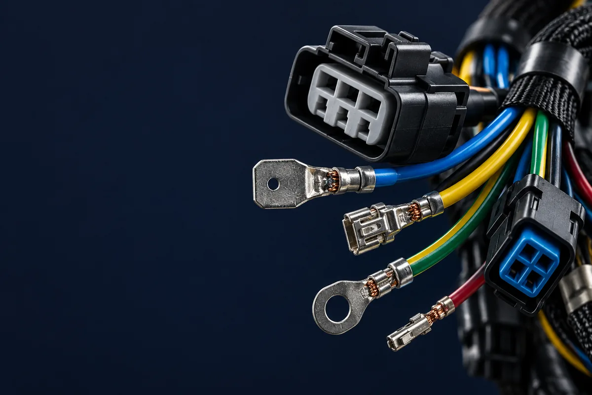
Direct answer: Verify a wire harness with visual inspection, a pin-to-pin netlist check for opens and shorts, and the electrical and mechanical tests required by its drawing. Continuity, contact resistance, insulation resistance and dielectric withstand answer different questions. Set their limits from the approved component specifications and assembly test plan, and retain measured results with the harness identification.
A wire harness might look perfect—neatly bundled, properly labeled, connectors firmly seated. But looks can be deceiving. Harnesses that pass visual inspection can still fail in the field when nobody runs a proper continuity test, and perfectly good harnesses get rejected when the test equipment's output is misread.
This guide separates the testing that is actually necessary from what is just expensive theater. Review the available testing scope at our manufacturing facility. This guide describes common testing methods—and more importantly, help you understand when each one actually matters.
Why Wire Harness Testing Actually Matters
Let's start with a reality check. Wire harnesses are the nervous system of modern equipment. They carry power, transmit signals, and connect systems. When they fail, consequences range from annoying (your dashboard lights flicker) to catastrophic (your transit vehicle loses critical systems).
| Failure Stage | Cost Impact | Time to Fix | Possible Consequence |
|---|---|---|---|
| During Manufacturing | Internal rework cost | Depends on rework scope | Rework before shipping |
| At Customer Receiving | Return and replacement cost | Depends on investigation | Return, investigation, replacement |
| During Assembly | Assembly disruption cost | Depends on replacement scope | Line shutdown, expedited replacement |
| In Field | Field service or recall exposure | Depends on field action | Recall, liability, reputation damage |
Testing can reduce downstream rework and failure costs, depending on the defects it detects. But here's what most articles won't tell you—not every harness needs every test. A 3-wire harness for a desk lamp doesn't need the same testing regimen as a 500-circuit automotive harness . Understanding which tests to apply and when is where the real expertise lies.
Visual Inspection Methods
Visual inspection is the foundation of all quality control. Before you hook up expensive test equipment, a trained inspector can identify visible workmanship defects. The key word is "trained"—an untrained inspector misses obvious problems while flagging non-issues.
What to Look For
Wire & Insulation
- Insulation cuts, nicks, or abrasion
- Heat damage (discoloration, melting)
- Correct wire gauge per spec
- Proper color coding
Connectors & Terminals
- Terminal fully seated (click test)
- No bent or damaged pins
- Correct pin position per drawing
- Proper locking mechanism engagement
Crimp Inspection: The Critical Detail
Bad crimps can contribute to field failures. Here's what a good crimp looks like:
| Crimp Characteristic | Acceptable | Reject |
|---|---|---|
| Wire conductor visibility | Visible in inspection window | None visible or strands outside |
| Bellmouth | Slight flare at entry (trumpet shape) | No bellmouth or excessive flare |
| Insulation grip | Wrapped around insulation, not cutting | Loose or cutting into insulation |
| Wire brush | Wire extension per terminal specification | No extension or excessive length |
Electrical Testing: The 4 Essential Tests
Electrical testing verifies that your harness will actually function correctly. While visual inspection catches physical defects, electrical testing catches functional defects that are invisible to the eye.
1 Continuity Testing (Pin-to-Pin)
The most fundamental electrical test. It verifies that electricity can flow from point A to point B through the wire. Simple concept, critical results.
What It Catches
- • Open circuits (broken wires)
- • Short circuits (wires touching)
- • Miswires (wrong pin positions)
- • Missing connections
How It Works
- • Apply a test voltage approved for the assembly and connected components
- • Measure current flow between pins
- • Compare to expected circuit map
- • Flag any deviations
When to use: Define continuity coverage in the approved test plan for a professional wire harness manufacturer .
2 Contact Resistance Testing
Continuity tells you IF current flows. Resistance testing tells you HOW WELL it flows. A connection can be "continuous" but still have dangerously high resistance that causes heat buildup and eventual failure.
| Resistance Reading | Status | Likely Cause |
|---|---|---|
| Within the approved resistance limit | Good | Consistent with the approved test criteria |
| Near the approved limit or inconsistent on retest | Marginal | Investigate—possible loose crimp |
| Exceeds the approved resistance limit | Reject | Investigate crimp, corrosion, damage, and fixture effects |
When to use: High-current applications, automotive, industrial, any circuit where resistance-induced heat could cause problems.
3 Insulation Resistance Testing (IR/Megger)
While continuity tests the wire, insulation resistance tests the insulation. It applies high voltage between the conductor and ground to ensure the insulation can handle its rated voltage without leaking current.
Specification Checks
- • Test voltage: Per approved test plan
- • Minimum acceptable: Per component and assembly specification
- • Good quality: Evaluate against the approved resistance limit
- • Test duration: Per approved test procedure
What It Catches
- • Damaged insulation
- • Moisture contamination
- • Manufacturing residue
- • Insulation degradation
When to use: All medium and high-voltage applications, humid environments, medical devices , industrial equipment.
4 High Potential Testing (Hipot)
The hipot test is the heavy artillery of electrical testing. It applies voltage significantly higher than operating voltage to stress-test the insulation. Passing a hipot test demonstrates performance under that test’s conditions; it does not guarantee service life or behavior under every operating condition.
| Application | Operating Voltage | Hipot Setting to Confirm | Duration |
|---|---|---|---|
| Consumer Electronics | Per product rating | Per applicable product test plan | Per approved procedure |
| Industrial Equipment | Per product rating | Per applicable product test plan | Per approved procedure |
| EV High-Voltage | Per platform rating | Per approved HV test plan | Per approved procedure |
| Medical Devices | Varies | Per applicable medical-device test plan | Per approved procedure |
⚠️ Safety Warning: Hipot testing involves dangerous voltages. Only trained personnel should perform these tests using properly calibrated equipment with appropriate safety interlocks.
| Test Type | Cost | Time | Required? |
|---|---|---|---|
| Continuity | $ | Seconds | Per approved control plan |
| Resistance | $$ | Seconds | High current apps |
| IR/Megger | $$ | Per approved dwell | Medium/high voltage |
| Hipot | $$$ | Per approved dwell | Safety critical |
A Component-Specific Electrical Test Reference: JST XH
The JST XH catalog provides a concrete way to distinguish three electrical acceptance quantities. All values below are reference values for this connector family; use the specific model's datasheet and approved test procedure. They do not automatically become complete-harness production settings. Source: JST XH manufacturer catalog, page 1.
| Quantity | Published specification | What the test plan must distinguish |
|---|---|---|
| Contact resistance | 10 mΩ maximum initially; 20 mΩ maximum after environmental tests | Initial acceptance versus the specified post-environment condition |
| Insulation resistance | 1,000 MΩ minimum | Resistance limit versus the separately approved test voltage and dwell |
| Dielectric withstand | 1,000 VAC for one minute, without breakdown or flashover | Withstand voltage and time versus normal working voltage |
Contact-resistance check: define the sense points and account for fixture and lead contributions before comparing a measurement with the connector limit. A complete wire path includes conductor resistance, so applying the connector number to an entire harness can reject an otherwise acceptable assembly.
Insulation-resistance check: the catalog summary does not specify an IR test voltage or dwell. Obtain those conditions from the applicable manufacturer procedure and assembly test plan before programming the tester. A resistance number alone is not a reproducible test recipe; document the tested pin groups and any excluded electronic components.
Withstand check: XH's published working rating is 250 V AC/DC, distinct from its withstand test. Do not infer a production leakage-current limit or an operating voltage from the 1,000 VAC figure. Approve ramp, dwell, trip criteria, fixture clearances and component isolation for the actual assembly before using a high-voltage program.
Mechanical Testing: Will It Survive the Real World?
Electrical and mechanical tests evaluate different requirements. Passing a bench test does not establish durability under the application’s vibration and flexing conditions.
Pull Force Testing (Crimp Strength)
Pull force testing is one method of evaluating crimp mechanical strength. A properly crimped terminal should withstand specific force levels before the wire pulls out. Use the customer-invoked IPC/WHMA-A-620 revision and class, terminal specifications, and approved test procedure to select the applicable pull-force criteria.
| Wire Gauge (AWG) | Minimum Pull Force (lbs) | Minimum Pull Force (N) |
|---|---|---|
| 26 AWG | Per governing specification | Per governing specification |
| 22 AWG | Per governing specification | Per governing specification |
| 18 AWG | Per governing specification | Per governing specification |
| 14 AWG | Per governing specification | Per governing specification |
| 10 AWG | Per governing specification | Per governing specification |
Crimp Cross-Section Analysis
This is destructive testing at its finest. A prepared crimp cross-section is examined under a microscope to inspect internal features:
Good Cross-Section Shows
- All strands captured and compressed
- Uniform compression across section
- Void criteria per the approved crimp specification
- Proper crimp height (per spec)
Bad Cross-Section Shows
- Loose or missing strands
- Over/under compression
- Insulation in conductor area
- Cracked barrel or broken strands
Environmental Testing: Evaluating Service Conditions
Environmental testing exposes harnesses to specified stresses; translating results into service life requires a validated model and application data. This is especially critical for automotive and industrial applications where harnesses face extreme conditions.
| Test Type | Conditions | Duration | What It Reveals |
|---|---|---|---|
| Thermal Cycling | Temperature profile per qualification plan | Cycles per approved plan | Solder joint cracks, insulation brittleness |
| Humidity Exposure | Temperature and humidity per approved plan | Duration per approved plan | Corrosion, insulation absorption |
| Salt Spray | Salt-fog method per governing standard | Duration per approved plan | Terminal corrosion, plating quality |
| Vibration | Frequency and acceleration per approved profile | Duration per approved profile | Fretting corrosion, fatigue failures |
| Flex/Bend | Bend geometry per motion profile | Cycle target per application requirements | Wire fatigue, strain relief failure |
Not every harness needs full environmental testing. Salt-spray testing may be unnecessary for an indoor harness without relevant exposure or a customer requirement. But if your harness is going under the hood of a car or into robotic equipment that flexes constantly, these tests are essential.
Functional Testing: The Final Proof
Functional testing goes beyond verifying individual circuits—it tests the harness in actual operating conditions or a simulation thereof. This catches integration issues that component-level testing misses.
Functional Testing Methods
In-Circuit Testing
Connect the harness to a test fixture that simulates the actual loads and verify proper operation of all circuits under realistic conditions.
- • Verify relay/switch operation
- • Check signal integrity
- • Measure voltage drops under load
End-of-Line Testing
Final test performed on every harness before shipping. Combines multiple tests into a single automated sequence.
- • Automated continuity check
- • Quick hipot (if required)
- • Basic functional verification
Testing Equipment Guide: What You Actually Need
The right equipment depends on your volume and complexity. Here's a practical guide based on production levels:
| Equipment | Cost Range | Best For | Leading Brands |
|---|---|---|---|
| Digital Multimeter | Request current equipment quote | Prototype, low volume | Fluke, Keysight, Hioki |
| 4-Wire Milliohm Meter | Request current equipment quote | Crimp resistance testing | Hioki, Keithley |
| Manual Test Board | Quote fixture and test scope | Low-medium volume | Custom built |
| Automated Cable Tester | Quote system and channel count | Medium-high volume | Cirris, DIT-MCO, CableEye |
| Hipot Tester | Quote voltage and safety options | Safety-critical applications | Associated Research, Chroma |
| Pull Force Tester | Quote range and accessories | Crimp validation | Imada, Chatillon, Mark-10 |
| Cross-Section Microscope | Quote preparation and imaging system | Process validation | Keyence, Nikon, Olympus |
IPC/WHMA-A-620 Standards: The Industry Bible
IPC/WHMA-A-620 is a widely used cable and wire harness workmanship standard. If you're serious about quality—or your customers require certified quality—you need to understand and follow this document. Learn more about essential certifications for wire harness manufacturers.
A-620 Class Levels
| Class | Application | Inspection Level |
|---|---|---|
| Class 1 | General electronic products | Apply invoked Class 1 acceptance criteria |
| Class 2 | Dedicated service electronics | Apply invoked Class 2 acceptance criteria |
| Class 3 | High-performance electronics | Apply invoked Class 3 acceptance criteria |
Confirm the required IPC/WHMA-A-620 class and revision with the customer. Product sector alone does not establish the applicable acceptance class.
In-Process vs Final Inspection: Both Matter
A common mistake is relying only on final inspection. By the time a harness reaches final test, defects are expensive to fix. The smart approach is layered inspection throughout the process.
| Stage | Tests Performed | Frequency |
|---|---|---|
| Incoming Material | Visual, dimensional, CoC review | Every lot |
| Setup Verification | First article, cross-section, pull test | Each setup, shift start |
| In-Process | Visual, crimp height monitoring | Every piece or sampling |
| Sub-Assembly | Partial continuity, visual | After each build stage |
| Final Test | Full continuity, hipot, functional | 100% of production |
| Outgoing QC | Visual, labeling, packaging | 100% or AQL sampling |
Common Defects and How to Catch Them
The following defects can occur in harness production; select detection methods appropriate to the drawing and test plan:
| Defect | Root Cause | Best Detection Method |
|---|---|---|
| Wrong pin position | Human error during insertion | Automated continuity test |
| Bad crimp | Tool wear, wrong setting | Cross-section + pull test |
| Damaged insulation | Handling, routing, stripping | Visual + hipot test |
| Terminal not fully seated | Insertion technique | Visual + retention force test |
| Wrong wire | Material mix-up | Automated continuity + visual |
| Missing component | Human error | Visual inspection checklist |
Building Your Testing Program: A Practical Approach
Don't try to implement everything at once. Start with the basics and build up based on your specific needs and customer requirements.
Level 1: Minimum Viable Testing
- ✓ 100% visual inspection
- ✓ 100% continuity testing
- ✓ First article inspection
Level 2: Standard Quality
- ✓ All Level 1 tests
- ✓ Destructive pull testing on approved samples
- ✓ Cross-section analysis at setup
- ✓ In-process inspections
Level 3: High Reliability
- ✓ All Level 2 tests
- ✓ Hipot testing
- ✓ Contact resistance testing
- ✓ Environmental testing (qualification)
Level 4: industrial/Medical Grade
- ✓ All Level 3 tests
- ✓ Pull-test sampling per approved plan
- ✓ Full documentation package
- ✓ Statistical process control
- ✓ Functional testing
Conclusion: Quality is a Process, Not an Inspection
The best testing program in the world can't fix a broken manufacturing process. Testing should verify quality that's built in, not try to inspect quality into a product. When you're finding defects at final test consistently, that's a signal to fix the process, not add more tests.
At the same time, even the best processes produce occasional defects. That's why testing remains essential—it's your last line of industrial before a defective product reaches your customer.
If you're looking for a wire harness manufacturer with comprehensive testing capabilities, ask the right questions about their quality program . Confirm the equipment, trained personnel, and documented test scope available for your project.
Frequently Asked Questions
What tests are used for wire harness quality control?
Core tests include continuity to confirm correct point-to-point wiring, hipot/dielectric withstand, insulation resistance, crimp pull-force, and where relevant IP or leak testing. The combination verifies both electrical integrity and mechanical robustness.
What is hipot testing?
Hipot, or dielectric withstand testing, applies a high voltage between conductors and ground to confirm the insulation can withstand stress without breakdown. It catches insulation defects and clearance problems that a continuity test would miss.
What is a crimp pull-force test?
It measures the force required to separate a crimped terminal from its wire, verifying that the crimp meets the mechanical strength specified by the standard. A below-limit result requires investigation of the crimp, tooling, material combination, and test setup.
Is 100% testing necessary for wire harnesses?
Agree on per-unit testing or sampling with the customer based on risk, component requirements, and the approved control plan. Destructive tests generally require a separate sampling plan.
What standards govern wire harness testing?
Acceptance is generally driven by IPC/WHMA-A-620 along with the customer's specific test specification. Apply the acceptance criteria for the customer-invoked class and revision alongside the assembly-specific test requirements.
Do you provide test reports with shipments?
Yes. Test data and certificates of conformance can accompany shipments, giving you documented evidence that each harness met its electrical and mechanical acceptance criteria.