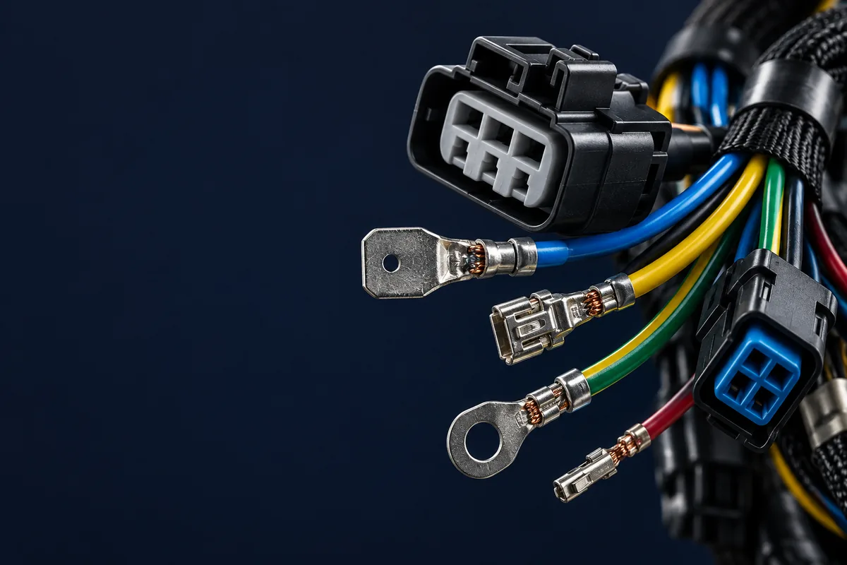
Direct answer: Inspect a wire harness against the contract-specified IPC/WHMA-A-620 revision and class, the released drawing, and the terminal manufacturer's application specification. Check wire preparation, termination geometry, assembly protection and identification, then document the required electrical and mechanical test results. A visual pass alone does not establish that a crimp meets its dimensional or pull-force requirements.
You received a batch of wire harnesses from your supplier. They look fine to the naked eye. But do they actually meet workmanship standards? Without a systematic inspection framework, “looks fine” is not a quality strategy—it’s a liability.
IPC/WHMA-A-620 describes, in IPC’s words, “materials, methods, tests and acceptance criteria for producing crimped, mechanically secured and soldered interconnections and the related assembly activities associated with cable and harness assemblies.” IPC lists Revision F, published 1 October 2025, as the current revision; it follows Revision E, which IPC released on 22 December 2022. Your contract should name the revision you inspect to, because acceptance criteria can change between revisions. This guide turns the inspection workflow into records and questions you can use on the production floor; it does not reproduce the standard’s tables, which you need the controlled document for.
Three Controls to Add to the Inspection Plan
1. Define inspection frequency explicitly. IPC's overview states that IPC/WHMA-A-620 does not specify the frequency of in-process or product inspection. The control plan must therefore identify which checks occur at setup, during production and at final release, together with the sampling rule and reaction to failure. Record the agreed standard revision and class on the inspection record. Source: IPC standards overview.
2. Attach the component-specific dimension sheet. For the listed Molex Mini-Fit Jr. 5556 series terminals processed with tool 63819-0900, application sheet ATS-638190900, Revision H, page 3 gives a 20 AWG conductor crimp-height reference range of 0.83–0.93 mm. Reference values: use the exact terminal and tool datasheets; this is not a universal IPC height tolerance. Add terminal order number, wire construction and measured height to the record so the inspector can identify which reference applies. Source: Molex tool application sheet.
3. Inspect wire preparation against the same tool/terminal pairing. The same sheet lists 3.00–3.30 mm strip length for its covered terminals and recommends 1.70–2.30 mm overall insulation diameter for the 20–24 AWG tool profile to achieve Class 2 crimps. These are model-specific reference values. A wire substitution can keep the AWG unchanged while changing insulation fit; verify the approved pairing before accepting the first article. Source: Molex application sheet, pages 1–3.
What Is IPC/WHMA-A-620?
IPC/WHMA-A-620 (commonly called “IPC-620”) is the requirements and acceptance standard for cable and wire harness assemblies. Developed jointly by IPC (Association Connecting Electronics Industries) and WHMA (Wiring Harness Manufacturer’s Association), it covers materials, methods, tests, and acceptance criteria for crimped, mechanically secured, and soldered interconnections.
Unlike general quality management standards like ISO 9001 or IATF 16949, IPC-620 is a workmanship standard. It does not tell you how to organize your quality system. It tells you exactly what a properly crimped terminal, a correctly routed harness, and a compliant solder joint should look like—illustrated with photographs and drawings for many of its criteria.
What IPC-620 Covers
Per IPC’s description, the standard addresses four things for three kinds of interconnection — crimped, mechanically secured and soldered — plus the related assembly activities for cable and harness assemblies:
Materials
the wire, terminals, insulation and protective materials used in a cable or harness assembly
Methods
how the interconnections and related assembly activities are carried out
Tests
the checks used to verify an assembly
Acceptance criteria
what counts as acceptable, a process indicator, or a defect, by class
Source: IPC standard descriptions (IPC store, IPC news release for Revision E). Revision E changes IPC listed: a new chaptering system, added figures, alignment of soldering requirements with IPC J-STD-001, a revised Circular Mill Area, and updated Appendix A definitions.
The 3-Class System Explained
IPC-620 uses a three-class system to define the level of workmanship required. The class determines which criteria are “acceptable,” which are “process indicators,” and which are outright “defects.” Your customer’s contract or purchase order should specify the required class. Because the criteria differ by class, state the class in writing on the purchase order and the drawing rather than leaving it to assumption.
| Criteria | Class 1 | Class 2 | Class 3 |
|---|---|---|---|
| Class name (as commonly cited) | General electronic products | Dedicated service electronic products | High performance electronic products |
| What the class is about | Function is the main requirement | Extended life and continued performance are required; uninterrupted service is not critical | Continued performance is critical; downtime cannot be tolerated; the product may face a harsh environment |
| How the criteria compare | Least demanding | More demanding than Class 1 | Most demanding |
| Who chooses the class | The customer, in the contract, purchase order or drawing | The customer, in the contract, purchase order or drawing | The customer, in the contract, purchase order or drawing |
Key Distinction: Process Indicator vs. Defect
The standard describes conditions in terms such as acceptable, process indicator (not a reject, but a sign the process needs attention) and defect (does not meet the requirement). How a given condition is classified can differ by class, so read the criterion for your class and revision in the standard rather than relying on a summary.
Crimp Inspection Criteria
Crimping is one of the most critical processes in wire harness manufacturing. A good crimp creates a gas-tight connection between conductor and terminal. A bad crimp creates an intermittent failure waiting to happen.
Open Barrel Crimp — Visual Criteria
The lists below are a practical visual checklist of conditions commonly looked for on an open barrel crimp. They are not a substitute for the standard: the exact acceptance limits, and which conditions are acceptable or a defect for your class, are in the standard’s tables for your revision.
Typically acceptable
- Wire strands visible at inspection window
- Bellmouth present on wire entry side
- Crimp impression centered on barrel
- No insulation trapped in conductor crimp area
- Insulation crimp securely grips insulation
Typically a defect
- Crimp applied to insulation instead of conductor
- No conductor strands visible at inspection window
- Cut or nicked strands exceeding class limit
- Crimp not fully compressed (loose barrel)
- Wire extends beyond crimp barrel into contact area
Crimp Height & Pull Force Testing
Visual inspection alone does not confirm a crimp. Measure crimp height with a micrometer suited to the terminal (not calipers) and compare it with the terminal manufacturer’s application specification, and pull-test crimped samples against the required minimum for the wire size. Minimum pull force is set by the table in the standard revision you are inspecting to, and by the terminal manufacturer’s specification where that is stricter; UL 486A-B also carries pull-out requirements for wire connectors.
This guide does not list pull-force numbers. Published tables in secondary sources disagree with each other, so use the table in your controlled copy of the standard and the terminal datasheet. Force is reported in newtons or pounds-force (1 lbf = 4.448 N), so record the unit next to every number. How often to test is your control plan’s decision, as covered above, not something IPC sets for you.
A pull-test record that stands up to an audit:
| Field | What to record |
|---|---|
| Terminal and tool | Terminal part number, tool or die number, applicator or hand tool ID |
| Wire | Gauge, strand count, insulation type and outside diameter |
| Required minimum | Value and unit, with the document it came from (standard revision and table, or terminal datasheet and revision) |
| Result | Measured force, unit, and where the wire failed (wire break, pull-out, terminal deformation) |
| Sample point | Setup, in-process or final, and the sampling rule from the control plan |
| Verdict and disposition | Accept or reject, inspector, date, and action taken on a failure |
High-reliability programs often add crimp force monitoring (CFM) on the press so every crimp is checked, not only sampled parts; whether that is required is a customer or program decision. For more on the process behind these checks, see our wire harness crimping guide and the wire harness quality testing guide.
Solder Termination Inspection
IPC-620 aligns its soldering requirements with IPC J-STD-001 (Requirements for Soldered Electrical and Electronic Assemblies). When a wire harness includes soldered terminations—cup terminals, turret terminals, or PCB connections—the solder joint quality criteria apply.
Solder Cup Terminal Criteria
A practical checklist of common conditions; the acceptance limits for your class and revision are in the standard’s tables.
Typically acceptable
- Solder fill meets the minimum in the standard’s table for your class and revision
- Smooth, shiny or satin solder fillet
- Wire visible at top of cup
- No cold solder joints (grainy, dull surface)
Typically a defect
- Solder fill below the class minimum in the standard
- Solder bridges between adjacent cups
- Fractured or disturbed solder joint
- Insulation melted or charred from heat
Wire Preparation & Damage Limits
Wire preparation is where many defects originate. Automated stripping machines can nick conductors. Manual stripping can cut too deep. The standard sets limits on how much conductor damage is permissible, and the allowable amount depends on the wire size and the class.
For a deeper dive into conductor and insulation materials and how they affect strippability, see our wire harness materials guide.
Strand damage and strip checks: how to record them
The allowable amount of nicked or cut strands depends on the wire size, the strand count and the class, and it is read from the table in the standard revision you inspect to. Count the damaged strands and compare with that limit. Strip length and insulation fit are set by the terminal and tool pairing (see the Molex example above), not by IPC alone.
| Check | How to verify | Record |
|---|---|---|
| Strand damage | Count nicked or cut strands against the total in the conductor; compare with the limit in the standard for the wire size and class | Wire, strand count, damaged count, class, limit and its source |
| Strip length | Measure with a gauge or scale against the terminal application specification | Measured length, required range, terminal part number |
| Insulation fit | Confirm the insulation diameter suits the terminal’s insulation grip range for the approved wire | Wire outside diameter, terminal, tool profile |
| Conductor condition | Look for stray strands, bird-caging, discoloration or contamination | Pass or fail, with a photo for any reject |
Harness Assembly & Protection
Once wires are terminated, they must be routed, bundled, and protected according to the assembly drawing. IPC-620 covers lacing, cable ties (tie wraps), taping, braided sleeving, conduit, heat shrink tubing, and strain relief.
Cable Tie (Tie Wrap) Inspection
A practical checklist of common conditions; the acceptance limits for your class and revision are in the standard’s tables.
Typically acceptable
- Tie is snug but does not deform insulation
- Tail trimmed flush (no sharp edge)
- Positioned per the drawing, within the drawing tolerance
- Lock mechanism fully engaged
Typically a defect
- Tie over-tightened causing insulation damage
- Tail longer than the drawing or standard allows, creating a snag hazard
- Tie placed over splice or branch point incorrectly
- Lock not fully engaged (tie can rotate freely)
Heat Shrink Tubing
Heat shrink must fully recover (shrink) to conform tightly to the underlying surface. Acceptance checks include no splits, cracks, or charring; uniform shrinkage with no bridging over air gaps; and overlap and sealing as the drawing and the standard’s table for your class require. Where the drawing calls for an environmental seal, specify adhesive-lined heat shrink and inspect the adhesive flow at both ends.
Routing & Bend Radius
Wire routing must follow the assembly drawing. Do not bend below the cable manufacturer’s minimum bend radius, which is on the cable datasheet (for coaxial cable in particular, the datasheet value governs). Sharp bends, kinks, or wires crossing over sharp edges without protection are defects in all classes. Learn more about proper harness design in our wire harness design guide.
Labeling & Marking Requirements
Labels are not an afterthought—they are part of a conforming assembly. The standard includes marking and labeling criteria, and a label that cannot be read or does not stay on is a quality problem. For regulated industries like medical devices and automotive, label traceability is a compliance requirement.
Practical IPC-620 Inspection Checklist
Use this checklist as a starting point for incoming inspection or in-process quality audits. Customize it based on your specific product class and customer requirements.
- Are the inspection plan and inspection frequency defined, and are the agreed standard revision and class recorded on the inspection record?
- Is the component-specific dimension sheet for the actual terminal and tool on file?
- Was crimp height measured with a micrometer (not calipers) and compared with the terminal manufacturer’s specification?
- Was a pull-force test done at the points your control plan requires, with the minimum, the unit and its source recorded?
- Are strands visible in the inspection window, is the bellmouth present on the conductor entry side, and is the crimp impression centered, with no insulation trapped in the conductor crimp?
- Does solder fill in solder cups meet the minimum in the standard’s table for the required class?
- Were strands checked for damage from stripping against the limit for the wire size and class?
- Is each cable tie positioned within the drawing tolerance, with the lock fully engaged and the tail trimmed?
- Does heat shrink at splices meet the drawing’s overlap, and is adhesive-lined heat shrink used where an environmental seal is specified?
- Is every bend at or above the cable manufacturer’s minimum bend radius?
- Are markings legible, durable and correctly positioned?
IPC-620 Certification Levels
IPC offers certification to its standards, including IPC/WHMA-A-620, at several levels. IPC describes them as follows:
| Level | IPC’s description |
|---|---|
| CIS — Certified IPC Specialist | “Appropriate for any individual that will benefit by having a consistent understanding of the criteria in a standard.” Line operators, engineers and quality engineers are the typical audience. |
| CIT — Certified IPC Trainer | Authorized “to deliver and administer CIS or CID / CID+ training and certification examinations to individuals who wish to gain IPC Certification.” |
| MIT — Master IPC Trainer | “An optional designation that may be obtained by a Certified IPC Trainer (CIT).” It is not an independent certification. |
| CSE — Certified Standards Expert | “A subject matter professional with a high level of knowledge and understanding of a specific IPC standard or group of standards.” |
Source: IPC certification page (electronics.org/ipc-certifications). The IPC page we reviewed does not state a validity period, so check the issue date on each certificate rather than assuming one.
Questions worth asking a supplier:
- Which standard and revision is each certificate for, and when was it issued?
- How many certified specialists (CIS) work on the line you would be using, and are they current?
- Is there a certified trainer (CIT) in house, or is training done by an outside trainer?
- Will the class and revision you specify be written on the inspection record for every lot?
A single trainer who certified operators years ago is not the same as a team with current certificates. For more supplier evaluation criteria, see our guide to choosing a wire harness manufacturer and the overview of wire harness certifications.
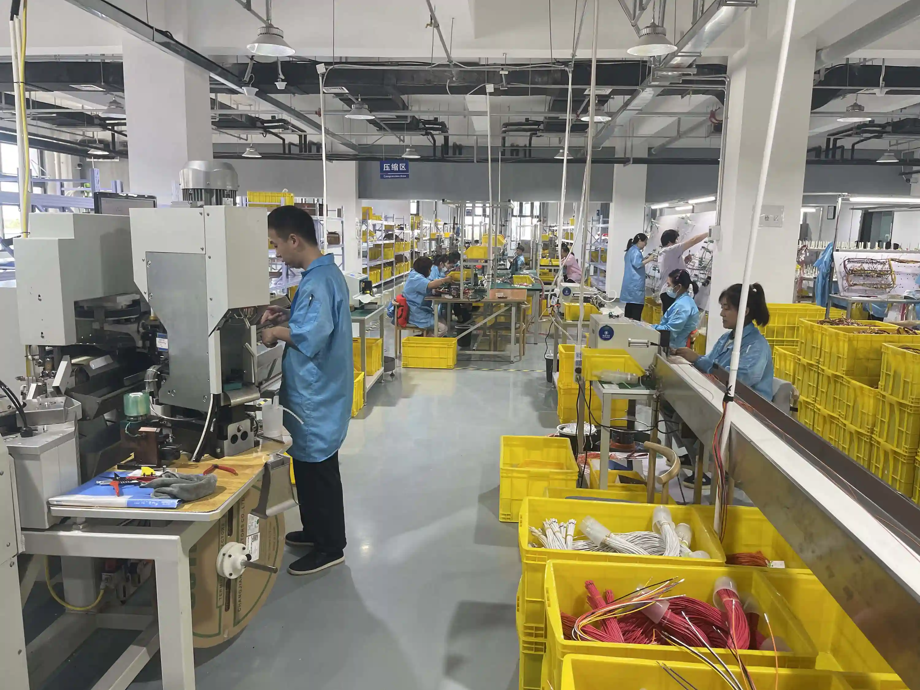
Precision wire cutting equipment calibrated to IPC-620 strip length tolerances
References
- IPC/WHMA-A-620 — Requirements and Acceptance for Cable and Wire Harness Assemblies (IPC store; Revision F is the current revision)
- EPTAC — Mastering Quality Standards: IPC 620 Certification in Electronic Manufacturing
- IPC — Certification levels (CIS, CIT, MIT, CSE)
- IPC — News release: IPC/WHMA-A-620E (22 December 2022)
- IPC/WHMA-A-620 Revision F listing (published 1 October 2025)
- Wiring Harness News — WHMA/IPC Releases IPC/WHMA-A-620 Rev E
Frequently Asked Questions
What is the difference between Class 1, 2, and 3 in IPC/WHMA-A-620?
Class 1 is general electronic products where the main requirement is function. Class 2 is dedicated service products needing extended life and reliable performance, such as industrial equipment. Class 3 is high-performance hardware where continued performance is critical, downtime cannot be tolerated and the environment may be harsh; its acceptance criteria are the most demanding. The customer chooses the class in the contract, purchase order or drawing.
Is IPC/WHMA-A-620 certification mandatory?
It is not a legal requirement, but it is often required by contract. Some customers ask their supplier to employ Certified IPC Specialists (CIS) and Certified IPC Trainers (CIT), and to build and inspect to a specified class and revision. Check your purchase order — the class and revision are usually called out there.
Which revision of IPC/WHMA-A-620 is current?
IPC lists IPC/WHMA-A-620 Revision F, published on 1 October 2025, as the current revision. It follows Revision E, which IPC released on 22 December 2022. Which revision applies to your parts is a contract matter: name it on the purchase order, and agree in writing before switching revisions on a running program.
What are the most common crimp defects found during inspection?
Typical crimp defects include insufficient conductor crimp (loose wire brush), insulation trapped inside the conductor crimp, missing or excessive bell-mouth, and wire strands cut or nicked during stripping. Crimp height and pull-force testing catch most of these before they reach final inspection.
Can I inspect to IPC/WHMA-A-620 without owning the standard?
Not reliably. The standard's value is its photographic acceptance criteria, so inspectors need access to the controlled document to make defensible accept/reject calls. Most manufacturers maintain a current copy on the floor and train inspectors against it rather than relying on memory.
What is the difference between IPC/WHMA-A-620 and IPC-A-610?
IPC/WHMA-A-620 covers cable and wire harness assemblies — crimps, splices, connectors, lacing, and overall harness workmanship. IPC-A-610 covers printed circuit board assemblies — solder joints, component placement, and PCB-level criteria. They are complementary standards for two different assembly domains.