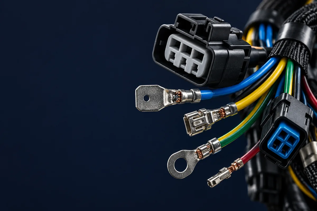
An engine wiring harness is the loom that ties an engine's sensors, actuators, ignition or injection, and charging circuits back to the ECU and power — and it lives in the harshest place on the machine. Heat, vibration, oil and coolant, chafe, and electrical noise all peak at the engine, so an engine harness is defined far more by its environment than by its circuit count. Specifying one well is a matter of heat-rated wire, sealed connectors, mechanical protection, and a build released to a workmanship standard. This guide covers what belongs on an engine harness and how to specify one so it survives and quotes cleanly.
TL;DR
- An engine harness connects engine-mounted sensors, actuators, ignition/injection, alternator and starter to the ECU and power.
- The under-hood environment — heat, vibration, fluids, chafe, EMI — drives every wire, insulation, connector and protection choice.
- Use temperature-rated automotive wire (for example TXL/GXL/SXL, or PTFE/silicone in the hottest zones), sized for current and derated for heat.
- Specify sealed, keyed connectors with the correct wire seals and cavity plugs; an unsealed connector in an engine bay is a failure waiting to happen.
- Release on crimp-height and pull-force records to IPC/WHMA-A-620, plus continuity and sealing checks — not on parts "clicking together".
What an engine wiring harness actually is
An engine wiring harness (often called an engine loom or engine management harness) is the bundle that carries every signal and power line an engine needs to run and be monitored. On a typical automotive, off-highway, or industrial engine that includes crank and cam position sensors, coolant and oil temperature and pressure sensors, the throttle or fuel-injection actuators, ignition coils or glow plugs, the mass-airflow or manifold-pressure sensor, plus the charging and starting circuits at the alternator and starter — all routed back to the engine control unit and the power distribution. It is usually built as an engine-mounted harness that mates to a chassis or body harness through a firewall bulkhead connector, so the split between what belongs on the engine and what belongs on the chassis is one of the first design decisions. The application context for this sits on our engine and starting harness page and the broader automotive wire harness work.
The engine-bay environment sets every choice
Nothing about an engine harness makes sense without the environment, because the engine bay is a genuinely hostile place for wiring. Four stresses dominate and each one filters the material choices:
- Heat. Ambient under-hood temperatures commonly sit around 105–125 °C, and surfaces near the exhaust manifold, turbo, or block run far hotter. Wire insulation and connector bodies must be rated for the zone they pass through, not the average.
- Vibration. An engine is a vibrating mass, so the harness sees constant mechanical cycling. Terminations, clips, and strain relief have to be designed for fatigue, not just for a single static fit.
- Fluids and chemicals. Oil, coolant, fuel, and cleaning chemicals attack the wrong insulation and unsealed connectors. Materials are chosen for fluid resistance and connectors for sealing.
- Chafe and EMI. Routing against sharp edges cuts insulation over time, and ignition and injector circuits generate electrical noise. Protection and sensible routing address both.
The practical rule is to design the harness for the worst zone each branch passes through. Treating an engine harness like a benign in-cabin harness is the most common and most expensive mistake — the difference in wire, connectors, and protection is exactly the difference between an automotive and an industrial harness, which our automotive vs. industrial wire harness guide compares in detail.
Wire and insulation for engine heat
Wire selection for an engine harness is a temperature decision first and a current decision second. Standard PVC-insulated wire is not suitable for most engine-bay routing; automotive thin-wall types such as TXL, GXL, and SXL (cross-linked polyethylene) offer higher temperature ratings and thinner walls, and the hottest branches — near the manifold, turbo, or ignition — often call for PTFE or silicone-insulated wire rated well above the ambient. Gauge is then sized for the current the circuit carries and derated for the elevated temperature and for being bundled, because a wire that is fine at room temperature can be marginal in a hot, tightly loomed branch. The current-and-gauge logic behind that sizing is covered in our connector and contact selection guide, and the insulation temperature class should be confirmed against UL 758 and the relevant automotive wire standard for the application.
Sealed connectors and terminals at the engine
Connectors are where an engine harness most often fails, because the engine bay is exactly the environment sealed connectors were built for. On-engine connections should use sealed, keyed connector systems with a peripheral seal, individual wire seals sized to the cable, and cavity plugs in every unused position — miss one and the seal is defeated. Terminal plating is chosen for the environment and mating cycles (tin for connectors that stay mated, gold where cycling or low-level signals demand it), and both halves of a mating pair should share the same plating. Sensor and actuator connectors are typically low pin-count sealed devices, while the bulkhead pass-through carries the highest pin count and the most sealing responsibility. The family logic for choosing among rugged sealed series is in our wire harness connector selection guide; for heavy machinery and off-highway engines, sealed families and heavier terminals are covered on our heavy equipment wire harness service.
Protection, routing, and strain relief
Protection is what turns the right wire and connectors into a harness that survives service life. Engine harnesses use convoluted (split) conduit for abrasion and heat resistance, braided or high-temperature sleeving near the hottest surfaces, and heat-reflective sleeving where a branch passes close to the manifold or turbo. Routing is fixed with clips, standoffs, and P-clamps so the harness cannot rub a moving or sharp edge or sag onto a hot surface, and service loops are left where the engine moves on its mounts relative to the body. Strain relief at each connector moves the flex point off the crimp so vibration does not fatigue the termination — the single detail that most often separates a harness that lasts from one that fails at the connector.
Build quality and release
An engine harness earns its reliability at the crimp and the seal, not at final assembly. Each terminated lead is crimped with the correct applicator and crimp height for the terminal, and the build is released on a pull-force result to the applicable class, 100% continuity, a sealing or IP check where the connector is sealed, and a visual inspection to IPC/WHMA-A-620 workmanship criteria. For a program that will reorder, that evidence and the harness configuration are recorded so a later build repeats the proven one. The crimp discipline behind this is in our wire harness crimping guide.
Representative project (anonymized)
Challenge. A United States machinery OEM had an active RFQ for heavy-equipment engine and power harnesses mid-evaluation when its primary sales contact left, putting the technical and quoting phase at risk of stalling. Approach. A structured, immediate handoff moved the account to a new manager who reviewed the wire specs, BOM, and quote status before proactively re-establishing contact, so the customer never lost technical or commercial continuity. Result. The evaluation continued without interruption and the sample quote for both harness types stayed active through the transition — 2 harness types in active quoting, zero RFQ interruption. The full write-up is in our machinery OEM sales-handoff case study.
How to specify an engine harness for an RFQ
An engine harness is quoted well when the environment and the interfaces are defined, not just the wiring list. A production-ready RFQ should carry:
- Schematic and connector list. Every sensor, actuator, and power connection with its connector and terminal part numbers, plating, and any approved alternate.
- Wire temperature class and gauge. The insulation type and rating for each zone, and the gauge or the current/temperature to size it against.
- Sealing and protection. Which connections are sealed, the conduit and sleeving type per branch, and heat-protection near hot surfaces.
- Routing, lengths, and fixing. Branch lengths with tolerances, clip and P-clamp positions, service loops, and the bulkhead split.
- Test and acceptance. Continuity, pull-force sampling, sealing check, and the acceptance class the harness is released to.
With those defined, an engine harness quotes against the real requirement and builds right the first time. The manufacturability side of that package is covered in our connector selection guide, and the case for keeping engine harnesses close to your program rather than treating them as a commodity is the theme of our engine and starting harness work.
Engine wiring harness FAQs
What is an engine wiring harness? It is the wiring loom that connects an engine's sensors, actuators, ignition or injection, and charging and starting circuits back to the ECU and power distribution. It is built to survive the heat, vibration, fluids, and electrical noise of the engine bay, and usually mates to the chassis harness through a firewall bulkhead connector.
What temperature rating does engine harness wire need? It depends on the zone. General under-hood routing uses cross-linked automotive wire such as TXL/GXL/SXL rated around 125 °C, while branches near the exhaust manifold, turbo, or ignition often need PTFE or silicone-insulated wire rated well above that. Size the gauge for current and derate it for the elevated temperature and bundling.
Why do engine harnesses use sealed connectors? Because the engine bay exposes connections to oil, coolant, fuel, washdown, and moisture. A sealed connector with wire seals and cavity plugs keeps those out of the contacts; an unsealed connector corrodes and fails. The seal is only complete when every unused cavity is plugged.
What is the most common engine harness failure point? The termination at a connector, when vibration fatigues a crimp that had no strain relief, or an unsealed connection that lets moisture reach the contacts. Correct crimp control, strain relief, and sealing — released to IPC/WHMA-A-620 — address the common failure modes directly.