The Short Answer: Specify the Interface Before the Mold
Overmolding forms a protective body around a cable termination to provide defined geometry, strain relief and, when designed and verified for it, environmental sealing. Choose it by checking the cable-jacket and resin pairing, the required loads and exposure, and the tooling economics. No material family or process name guarantees adhesion, flex life or an IP rating.
This guide turns those decisions into comparison tables, manufacturing checks and a specification checklist. The numeric cost example is explicitly hypothetical; material figures remain subject to the selected grade datasheet.
1. What Is Cable Overmolding?
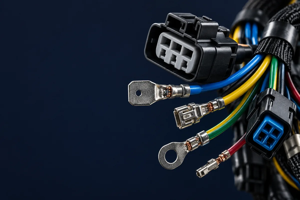
Cable overmolding forms a molded body around a prepared cable termination, connector or branch. The insert stays inside the finished part. The geometry can combine a grip, bend transition and environmental barrier. Overmolded cable assembly services should therefore be specified around the complete cable, connector and molded interface.
Thermoplastic compounds soften for injection and solidify during cooling. Liquid silicone rubber uses a different route: material cures in a heated mold. Neither process automatically establishes adhesion or a waterproof assembly. A molded body can be retained by material bonding, designed mechanical interlocks, or both; sealing requires separate verification.
Sources: Molex: insert-molding tool design; WACKER: silicone material and processing guidelines.
Start the drawing by separating three requirements: the load the termination must withstand, the movement the cable must accommodate, and the exposure the seal must resist. Give each its own acceptance criterion. A pull test alone should not be treated as evidence that the water barrier or flex transition has passed.
2. Overmolding vs Other Cable Protection Methods
Use the following as a selection worksheet. None of these method names specifies an achievable IP range. An IP67 or IP68 target must be tied to the actual construction, test conditions and assembly configuration. IEC 60529 classifies enclosure protection; it does not award a rating to a resin or process.
Sources: IEC 60529: enclosure protection classification.
| Method | Sealing / IP basis | Process and advantages | Limitations and suitable use |
|---|---|---|---|
| Overmolding | Can seal the cable transition; IP performance depends on design and validation. | Locate the assembly in a mold and inject material. Combines a defined external shape with strain relief. | Requires tooling and compatible processing conditions. Consider for repeat builds with a custom grip or bend transition. |
| Adhesive-lined heat shrink | The adhesive can provide a moisture barrier. The tubing alone supplies no assembly IP rating. | Heat the selected sleeve so it recovers around the joint. 3M SMS combines insulation, mechanical protection and strain relief. | Check recovery fit and installation instructions. Consider for splices and relatively simple transitions; it does not define a custom molded connector body. |
| Potting | Encapsulant can protect against moisture and chemicals. IP performance depends on the filled cavity and interfaces. | Dispense a selected compound and cure it. Henkel describes silicone, urethane and epoxy options for encapsulation. | Account for dispensing, void control and cure. Access to encapsulated parts is restricted. Consider for protected terminations inside a housing. |
| Separate strain-relief boot | Do not infer sealing from a boot. Specify a sealing system separately unless its documentation establishes one. | Fit a premolded accessory. TE describes flexible boots with internal cable grips for mechanical strain relief. | Match the boot, grip and cable diameter. Consider when an available accessory meets the geometry and retention requirements. |
Sources: Molex: insert-molding tool design; 3M: SMS adhesive-lined heat shrink; Henkel: potting compounds; TE: circular plastic connectors, flexible cable boots.
Compare alternatives against the same electrical and environmental requirements. For sleeve selection, see the heat-shrink tubing guide; for defining the complete sealing boundary, use the waterproofing and IP-rating guide.
3. The Overmolding Manufacturing Process
This six-stage workflow describes thermoplastic insert molding. The checks are a proposed control-plan structure, not universal acceptance limits. Set temperatures, pressure, drying and timing from the selected compound datasheet and qualified process. For silicone, replace thermoplastic cooling assumptions with the approved curing procedure.
| Stage | Operation | Quality gate / record |
|---|---|---|
| 1. Cable preparation | Cut, strip and terminate to the drawing; prepare clean bonding surfaces. Condition resin when its supplier requires it. | Check cable and resin identity, strip dimensions and termination workmanship. Record lots and applicable drying or cleaning checks. |
| 2. Connector positioning | Place the terminated connector into its locating fixture; establish orientation and cable exit direction. | Verify pinout and pre-mold electrical results, keying and contact seating. Confirm the fixture supports the insert without loading the joints. |
| 3. Mold loading and clamping | Seat the insert and cable in their locating features, protect mating surfaces, and close the tool. | Confirm cable location, shut-off fit and clear vents. Check that closure neither traps conductors nor damages the jacket. Record tool revision. |
| 4. Injection | Fill the cavity using the approved recipe while keeping the insert stable. | Record actual process settings against approved limits. Check trial pieces for incomplete fill, flash and insert movement before releasing the run. |
| 5. Holding and cooling | Apply the qualified holding stage, then allow the thermoplastic body to become stable enough for removal. | Confirm holding and cooling settings. During qualification, review dimensional stability and packing evidence; do not copy timing from an unrelated resin. |
| 6. Demolding and inspection | Remove the part without damaging the cable transition; finish it as the drawing permits. | Check dimensions, flash, exposed contacts and electrical function. Perform specified pull, flex and sealing tests under the agreed sampling plan. |
Sources: Avient: overmolding processing; Teknor Apex: adhesion explained; Molex: insert-molding tool design; ATL Medical: connector assembly process.
A useful lot record contains drawing revision, cable lot, resin grade and lot, tool/cavity identification, recipe revision, operator, electrical results and disposition. Define which checks apply to every assembly and which belong to qualification or sampling. The harness testing guide helps organize that discussion.
4. Material Selection Guide: TPU vs PVC vs TPE vs Silicone
Choose a compound, not just a polymer abbreviation. TPU is itself a thermoplastic elastomer; “TPE” below means other specified TPE families, rather than one interchangeable material. Compare jacket compatibility, exposure and bending behavior before approving a grade.
| Material | Jacket compatibility | Temperature range / limit | Chemical resistance | Flexibility |
|---|---|---|---|---|
| TPU | Qualify the exact jacket and molding grades; matching names alone do not establish adhesion. | Refer to the selected grade datasheet. | BASF describes oil/grease resistance; ether/ester formulation influences hydrolysis and chemical performance. | Elastic, abrasion-resistant options; select the grade and validate the actual bend geometry. |
| Flexible PVC | Supplier-matched molding and PVC jacket compounds are available; verify the pair. | Refer to the selected grade datasheet; do not use a universal PVC range. | Refer to the selected grade datasheet and fluid-specific test data. | Multiple hardnesses are available. For illustration, APEX 7500-70 lists nominal 70 Shore A at 15 seconds (ASTM D2240). |
| Other TPE families | Adhesion-modified grades target particular substrates. Obtain a written pairing recommendation. | Refer to the selected grade datasheet. | Resistance varies by formulation and exposure; test the actual chemicals and temperatures. | Compare flexural modulus and geometry, not hardness alone. Softness does not establish flex life. |
| Silicone rubber | Qualify the silicone/jacket pair and curing route; primer or surface treatment may be part of the system. | WACKER gives general family guidance of −50°C to +250°C. Typical guidance only; the selected grade datasheet and application validation govern. | WACKER warns of swelling in non-polar liquids such as hydrocarbons; assess the actual fluid. | Broad-temperature elastic behavior; review tear resistance and the finished transition, not just softness. |
Sources: BASF: Elastollan TPU properties; Teknor Apex: flexible PVC for electrical applications; Teknor Apex: APEX 7500-70 datasheet; Avient: TPE overmolding design guide; Avient: TPE and LSR performance comparison; WACKER: silicone material and processing guidelines.
The silicone range is material-family guidance, not permission to rate every connector, jacket or assembly to those endpoints. Likewise, a datasheet hardness is a specimen measurement, not a prediction of cable lifetime. Specify temperature duration, repeated bending and chemical exposure together. The thermal-management guide can help frame the operating conditions.
5. The Material Compatibility Trap
A smooth-looking interface is not proof of adhesion. Teknor Apex explains that substrate compatibility, contamination and processing affect bonding. Replace a blanket “same material always bonds” rule with a documented pairing and test record. A statement that TPU can never bond to PVC is also too broad without grade-specific evidence.
Sources: Teknor Apex: adhesion explained.
| Overmold material | TPU jacket | PVC jacket | Other TPE jacket | Silicone jacket |
|---|---|---|---|---|
| TPU | Requires sample validation | Requires sample validation | Requires sample validation | Requires sample validation |
| Flexible PVC | Requires sample validation | Chemical bonding is possible with suitable processing [A]; validate the exact pair. | Requires sample validation | Requires sample validation |
| Other TPE | Requires sample validation | Requires sample validation | Requires sample validation; identify both families and grades. | Requires sample validation |
| Silicone | Requires sample validation | Requires sample validation | Requires sample validation | Chemical bonding is possible [A]; validate grade, surface preparation and cure. |
[A] ATL’s materials discussion identifies PVC-over-PVC and silicone-over-silicone as possible chemical-bonding constructions. These examples do not establish universal compatibility. “Requires sample validation” means the reviewed sources do not establish a bonding route for the unspecified pair; it does not mean the pair is impossible.
Sources: ATL: Benefits of Overmolding Cables, Materials (printed page 9).
Choose and document the attachment route: chemical bonding at the interface; mechanical locking through suitable retention geometry; or bonding assisted by an approved primer or surface treatment. WACKER describes these routes for silicone, including self-adhesive grades and plasma treatment. None should be assumed to work on every jacket. Mechanical retention is not evidence of a watertight seal.
Sources: WACKER: silicone material and processing guidelines.
Ask for trial pieces made with production-intent cable, color compound and surface preparation. Record bond failure location, cable retention and seal results before and after the agreed environmental conditioning. Define the conditioning and acceptance criteria from the application; do not invent a universal thermal-cycle count. Freeze both material identities before tooling release.
6. Design Rules for Overmolded Cable Assemblies
Use these qualitative rules during design review. Avient supports uniform sections, gradual transitions, radii, draft, shut-offs and interlocks; Molex addresses cable and connector positioning. Final dimensions require the actual resin, insert tolerances and toolmaker review.
- Wall thickness: Keep sections reasonably uniform. Review thick pockets and thin flow paths instead of imposing one thickness on every material.
- Transitions: Use gradual section changes and rounded internal corners; avoid abrupt geometry that complicates flow or concentrates stress.
- Cable sealing: Define the bonded or separately sealed length and jacket condition. Review the full cable-diameter tolerance at the shut-off.
- Strain relief: Define the bend transition and installed routing envelope. Verify the cable supplier’s bend limits in the finished assembly.
- Draft and ejection: Provide release geometry appropriate to the resin, texture and draw depth. Agree how the assembly will leave the mold.
- Retention: Add interlocks where required for attachment. Avoid features that cut the jacket or obstruct the intended seal.
- Gates and vents: Review fill paths around inserts and trapped-air locations. Agree acceptable gate vestiges and keep critical interfaces clear.
- Parting lines and shut-offs: Identify sealing and mating surfaces on the drawing, then define acceptable flash and inspection access.
Sources: Avient: overmolding part design; Molex: insert-molding tool design.
These are review prompts, not dimensional acceptance tables. Use the strain-relief guide to document routing and load requirements, then approve the final drawing with the molder.
7. Tooling & Prototyping
Separate proof of fit from proof of process. Ask what a prototype will demonstrate: connector access, installed routing, adhesion, seal performance or production repeatability. A sample made by a different process should carry an explicit limitation on what it validates.
Molex describes aluminum tools for prototyping or lower-volume work and hardened steel for established higher-volume designs. Tool choice also depends on the molding material and required service life. Obtain a program-specific tool proposal rather than assigning one mold material solely from annual quantity.
Sources: Molex: insert-molding tool design.
- Tool scope: Identify inner and outer molds, cavities, cable-gripping inserts and any interchangeable features.
- Approval scope: Specify drawing review, first samples, inspection records and changes included before acceptance.
- Commercial scope: Record ownership, storage, maintenance, repairs, modification charges and release or transfer terms.
Discuss sample intent through the prototype assembly service. A published overmolded cable prototyping case provides related reading; its route is not a promised process or commercial term for another program.
8. Application Requirements to Bring to the Review
Use application labels to collect requirements, not to select a resin automatically. The following are specification prompts, not market-share claims or customer results.
- Robotics: Provide motion, routing, bend radius, torsion, expected duty and contamination details. Ask how the cable exit will be evaluated during repeated movement.
- Industrial equipment: List washdown conditions, oils or cleaners, installation loads and the connector’s mated or unmated exposure.
- Handheld equipment: Specify grip geometry, handling loads, cleaning agents and enclosure access requirements.
- Outdoor installations: Describe sunlight, water exposure, temperature changes and the required condition after environmental testing.
For other industry applications, prepare the same environment-and-load description. Avoid substituting an industry name for a measurable requirement.
9. Cost Analysis: Tooling, Per-Unit & Break-Even
Keep non-recurring engineering (NRE) separate from the recurring assembly price. For a simple comparison, let N be the agreed one-time tooling/development charge, Q the number of accepted assemblies over which it is allocated, and c the recurring cost per accepted assembly for the same scope.
Cost model
Total cost = N + Q × c
NRE per assembly = N / Q
Average cost = c + N / Q
Hypothetical example, not a supplier quote or market tooling price: Assume overmolding has N = $6,000 and c = $8. Assume an alternative has N = $0 and c = $11, and that both meet the same approved requirements. These invented inputs demonstrate the arithmetic only.
| Q | Overmold NRE / unit | Overmold average / unit | Overmold total | Alternative total |
|---|---|---|---|---|
| 500 | $12.00 | $20.00 | $10,000 | $5,500 |
| 2,000 | $3.00 | $11.00 | $22,000 | $22,000 |
| 5,000 | $1.20 | $9.20 | $46,000 | $55,000 |
For option A with higher NRE and lower recurring cost than B, Q at break-even = (NA − NB) / (cB − cA). Here, $6,000 / ($11 − $8) = 2,000 assemblies. If A also has equal or higher recurring cost, higher volume alone cannot recover its extra NRE in this model.
Use a consistent quotation scope: assembly, inspection, packaging and any expected loss already included in c. Add separately quoted qualification, shipping, maintenance or redesign charges when applicable. Do not assume a yield or field-failure saving. If future volume is uncertain, show several Q scenarios and identify who bears unrecovered tooling cost.
10. How to Specify an Overmolded Cable Assembly
Send the following alongside the wire harness RFQ checklist. This proposed checklist makes material and acceptance assumptions visible to potential manufacturing partners before they quote.
- Released assembly drawing, revision and overmold envelope.
- Cable manufacturer, part number, jacket compound and diameter tolerance.
- Connector and terminal part numbers, pinout and mating configuration.
- Termination details, shielding and pre-mold electrical tests.
- Overmold manufacturer and grade, color compound, and permitted alternates.
- Intended bonding or mechanical-retention route and trial evidence.
- Temperature, moisture, cleaning agents, oils and outdoor exposure.
- Pull, bending and torsional loads, routing and qualification conditions.
- IP target, sealing boundary, assembly configuration and test method.
- Dimensional, visual and electrical acceptance limits and sampling rules.
- Prototype purpose, tooling approval, ownership and maintenance terms.
- Order quantities, lifetime-volume assumptions, delivery and required records.
Require approval before changing the cable jacket, resin or preparation process. Ask how post-mold failures are dispositioned: access to encapsulated joints is restricted, so repairability must be established for the construction. Request evidence through the wire harness testing service rather than adding an arbitrary scrap allowance.
Frequently Asked Questions
Does overmolding automatically make a cable IP67 or IP68?
No. Specify the target and validate the complete sealing boundary in its intended configuration. A resin name or molded appearance is not an IP rating. Record the test conditions and any environmental conditioning required before testing.
Can TPU be overmolded onto a PVC jacket?
Do not assume either guaranteed bonding or guaranteed incompatibility from those names. Obtain grade-specific advice and make trial parts. Decide whether the design uses adhesion, mechanical retention or a separate seal, then validate that construction.
Which is better: TPU, PVC, TPE or silicone?
There is no universal winner. Compare the exact grades against the jacket, temperature, chemicals, bending and manufacturing process. Use supplier data to shortlist materials, then qualify the assembly rather than transferring material properties directly to the cable.
How is overmolding different from potting?
Overmolding uses a mold to define material around an insert, including the outer grip or strain-relief geometry. Potting fills a cavity with an encapsulant that cures. Choose according to the required geometry, protection and process, using the manufacturer references in the comparison table.
What minimum quantity makes overmolding economical?
There is no universal minimum. Compare quoted NRE and recurring costs at credible lifetime volumes. The hypothetical example here reaches equal total cost at 2,000 accepted assemblies; different assumptions produce a different result.
Can an existing connector be overmolded?
Possibly. Review the connector’s material and process limits, fixture support, mating surfaces and cable exit. Request a documented feasibility review and samples. Agree tooling lead time after that review instead of assuming a standard schedule.
Prepare an Overmolded Cable RFQ
Send the drawing, cable and connector part numbers, operating conditions and acceptance criteria for a scoped engineering review. Confirm material pairing, sample intent, tooling and validation responsibilities in the written quotation.
Contact the engineering team · Review manufacturing capabilities