Real Project Snapshot — Wire Harness Thermal Management Guide
Anonymized example from our case bank, shared so buyers can see how this scope is actually executed in production.
Industry: earthmoving-equipment | Region: Australia | Year: 2023 → 2024
Scenario: An Australian heavy machinery manufacturer requested quotes for multiple custom wire harness models but provided incomplete technical drawings at the initial inquiry stage.
Challenge: Missing critical specifications, including relay models, Deutsch connector models, and Hammond enclosure details, prevented accurate quoting and risked production errors for the 200-piece batch.
Solution: We implemented an engineering-to-engineering clarification process, compiling a detailed technical checklist to guide the client's internal engineering team to provide the missing specs, ensuring all requirements were locked down before sampling.
Result: Achieved full specification lock-down, enabling accurate quoting for 3 sample units and the 200-piece production run, preventing costly rework and material delays.
Concrete numbers: 3 sample units, 200-piece batch size, Deutsch connectors specified, Hammond enclosures specified
Wire Harness Thermal Management: Heat Dissipation, Derating & High-Temperature Design Guide
Heat is the silent killer of wire harnesses. Every degree above the insulation rating cuts service life in half. This guide covers ampacity derating calculations, insulation material selection (PVC vs XLPE vs PTFE vs silicone), bundling correction factors, heat dissipation strategies, and high-temperature design practices for automotive engine bays, EV battery packs, and industrial environments.
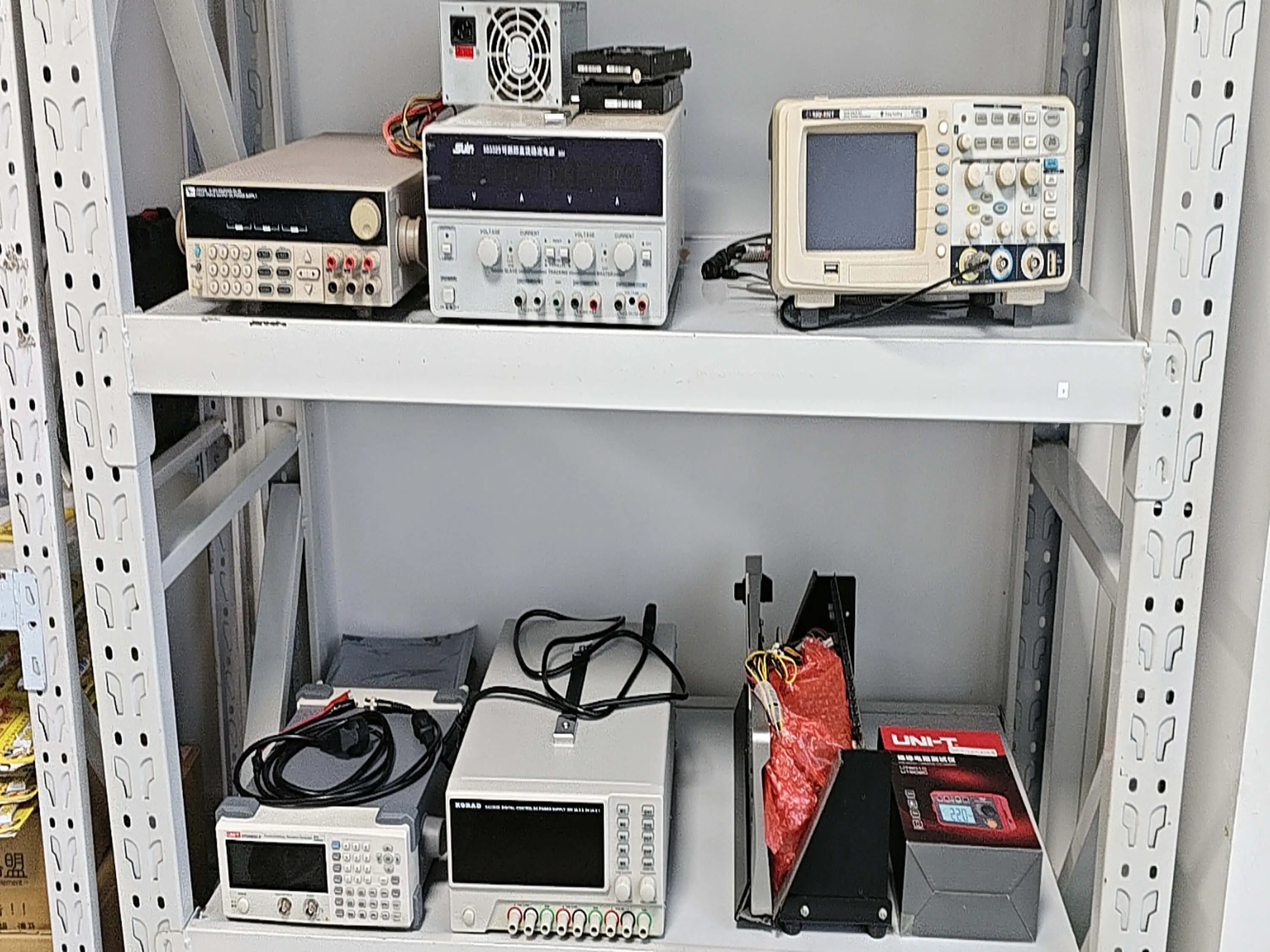
Comprehensive testing equipment used to validate wire harness thermal performance
insulation life lost per 10°C above rating
derating factor for bundles of 20+ conductors
maximum continuous rating for PTFE insulation
of field failures linked to thermal overload
Table of Contents
- 1. Why Thermal Management Matters for Wire Harnesses
- 2. Insulation Materials: Temperature Ratings and Trade-offs
- 3. Ampacity Derating: The Calculation Every Engineer Needs
- 4. Bundling Effects: How Grouping Wires Traps Heat
- 5. Heat Dissipation Strategies for Wire Harnesses
- 6. Thermal Design by Industry Application
- 7. Six Thermal Design Mistakes and How to Avoid Them
- 8. Frequently Asked Questions
Every wire carrying current generates heat. This is not a defect but a law of physics: I²R losses convert electrical energy to thermal energy in every conductor. In free air, a single wire dissipates that heat easily. Bundle fifty wires together inside a corrugated conduit routed through an engine compartment at 120°C ambient, and the thermal equation changes dramatically.
Thermal overload accounts for roughly 23 percent of wire harness field failures, second only to vibration fatigue and connector issues. The failures follow a predictable pattern: elevated temperature accelerates insulation aging, the insulation becomes brittle and cracks, adjacent conductors short, and the circuit fails—often months or years after installation when the damage becomes irreversible. The Arrhenius equation that governs polymer degradation is merciless: every 10°C above the rated temperature cuts insulation life approximately in half.
Preventing thermal failures requires getting three things right at the design stage: selecting insulation materials rated for your actual operating temperature (not just the ambient), properly derating wire ampacity for bundling and ambient conditions, and implementing heat dissipation strategies where routing near heat sources is unavoidable. This guide gives you the data, calculations, and practical techniques to get thermal design right on your next wire harness RFQ.
"The number one thermal mistake we see in wire harness RFQs is specifying wire gauge for the circuit current without accounting for how many other wires share the bundle. A 16 AWG wire rated at 22 amps in free air may safely carry only 11 amps when bundled with 20 other current-carrying conductors. Undersizing by even one gauge turns a reliable harness into a ticking clock."
Hommer Zhao
Engineering Director
1. Why Thermal Management Matters for Wire Harnesses
Wire harness thermal failures are insidious because they develop gradually. Unlike a mechanical failure that creates an immediate open circuit, thermal degradation weakens insulation progressively. The wire continues to function while its safety margin erodes. By the time intermittent faults appear, the insulation is already compromised across the entire thermal zone.
Heat in a wire harness comes from two sources: internal heating from current flowing through conductor resistance (I²R losses), and external heating from the operating environment. Internal heating is predictable and controllable through wire sizing. External heating depends on installation routing and is often the variable that designers underestimate.
The Arrhenius Rule: Temperature vs. Insulation Life
- At rated temperature: 20,000+ hour insulation life (typical)
- 10°C above rating: ~10,000 hours (50% reduction)
- 20°C above rating: ~5,000 hours (75% reduction)
- 30°C above rating: ~2,500 hours (87.5% reduction)
2. Insulation Materials: Temperature Ratings and Trade-offs
Selecting the right insulation material is the first and most impactful thermal design decision. Each material has a continuous temperature rating, a peak temperature tolerance, and trade-offs in flexibility, chemical resistance, cost, and wall thickness. The wire harness materials guide covers the full spectrum, but here we focus specifically on thermal performance.
| Material | Continuous (°C) | Peak (°C) | Flexibility | Cost Index | Best For |
|---|---|---|---|---|---|
| PVC | 80–105 | 120 | Good | 1.0x | General purpose, interior, low-cost |
| XLPE | 90–150 | 250 | Moderate | 1.5x | Automotive, under-hood, industrial |
| Silicone | 180–200 | 300 | Excellent | 3.0x | EV battery, flexible high-temp |
| PTFE (Teflon) | 200–260 | 300 | Low | 5.0x | Aerospace, exhaust-adjacent, chemical |
| FEP | 200 | 250 | Good | 4.0x | Aerospace, MIL-SPEC, plenum rated |
| Kapton (Polyimide) | 220–400 | 400 | Low | 8.0x | Extreme heat, aerospace, space |
Selection Rule of Thumb
Choose insulation rated at least 25°C above your maximum expected conductor temperature (ambient + I²R rise + safety margin). For applications with thermal cycling, add another 15°C margin because repeated expansion and contraction accelerate insulation aging beyond what steady-state temperature predicts.
3. Ampacity Derating: The Calculation Every Engineer Needs
Published wire ampacity ratings assume a single conductor in free air at 30°C ambient. Real wire harnesses violate all three assumptions: multiple conductors bundled together, enclosed in conduit or loom, at ambient temperatures well above 30°C. Ampacity derating accounts for these differences mathematically.
The Derating Formula
Ambient Factor (Fambient)
- 30°C ambient: 1.00
- 40°C ambient: 0.91
- 50°C ambient: 0.82
- 60°C ambient: 0.71
- 80°C ambient: 0.50
- 105°C ambient: 0.29
Bundling Factor (Fbundling)
- 1–3 conductors: 1.00
- 4–6 conductors: 0.80
- 7–9 conductors: 0.70
- 10–20 conductors: 0.50
- 21–30 conductors: 0.40
- 31+ conductors: 0.35
Enclosure Factor (Fenclosure)
- Free air: 1.00
- Open cable tray: 0.95
- Corrugated conduit: 0.85
- Sealed conduit: 0.75
- Buried/embedded: 0.60
Worked Example
Scenario: 16 AWG copper wire (free-air rating: 22A) in a bundle of 12 conductors inside corrugated conduit at 60°C ambient.
Iactual = 22A × 0.71 × 0.50 × 0.85
Iactual = 6.6A (only 30% of free-air rating)
This means the 16 AWG wire that was "rated" for 22A can safely carry only 6.6A in this installation. To carry the needed 10A, you would need to upsize to 12 AWG, which has a free-air rating of 41A and a derated capacity of 12.3A under the same conditions.
4. Bundling Effects: How Grouping Wires Traps Heat
Wire bundling is where most thermal problems originate. Conductors on the outside of a bundle can radiate heat to the surrounding air. Conductors in the center of a large bundle are insulated on all sides by adjacent wires, creating a thermal trap. Center conductors in a 30-wire bundle can run 20–40°C hotter than edge conductors carrying identical current.
Bundle Thermal Strategies
- Place highest-current conductors on the outside of the bundle where heat dissipation is best
- Split large bundles (>20 conductors) into smaller sub-bundles separated by 10–15mm air gaps
- Separate high-current power conductors from signal wires into dedicated bundles
- Use cable ties instead of continuous wrapping at bundle split points to allow airflow
Bundling Pitfalls
- x Counting only continuously loaded conductors—intermittent loads still generate heat
- x Ignoring bundling at harness junctions where branches merge into larger trunks
- x Using published derating for "number of conductors" but including non-current-carrying wires
- x Wrapping bundles tightly with vinyl tape that traps heat better than braided loom
5. Heat Dissipation Strategies for Wire Harnesses
When routing near heat sources is unavoidable, active and passive heat management strategies extend harness life. These range from zero-cost routing decisions to engineered thermal protection systems.
1. Routing and Clearance
The simplest and most effective thermal strategy is maintaining distance from heat sources. The inverse square law means doubling the distance from a radiant heat source reduces thermal load by 75 percent. Specify minimum clearances on assembly drawings: 50mm from exhaust manifolds, 25mm from turbocharger housings, 15mm from engine block surfaces.
2. Heat Shields and Reflective Wraps
Aluminum-faced fiberglass sleeving reflects radiant heat and insulates against conductive transfer. This is the standard protection for harness sections routed near exhaust systems. A single layer of aluminized heat shield reduces the effective heat load by 90 percent from radiant sources. For extreme exposure, dual-layer shields with an air gap provide superior protection.
3. Thermal Break Connectors
Inline connectors act as thermal breaks, preventing heat from conducting along copper conductors from a hot zone into a cool zone. Position a properly rated connector at the boundary between thermal zones. This also allows the high-temperature section to use PTFE or silicone insulation while the cool section uses lower-cost PVC, optimizing material costs.
4. Conductor Oversizing
Increasing conductor size by one or two AWG gauges reduces I²R heating proportionally. Moving from 18 AWG to 16 AWG for the same current reduces resistive heat generation by approximately 40 percent. The added material cost is typically $0.02–$0.05 per foot—trivial compared to a field failure. This approach is standard for EV high-voltage harnesses where thermal margins are critical.
5. Ventilated Conduit and Protective Sleeving
Corrugated split loom allows some air circulation between corrugations. Woven expandable sleeving (PET or Nomex) provides abrasion protection with significantly better airflow than sealed conduit. For highest heat dissipation, stainless steel braided sleeving combines mechanical protection with superior thermal conductivity that wicks heat away from the harness.
6. Thermal Design by Industry Application
Automotive Under-Hood
Ambient temperatures range from −40°C cold soak to 150°C near exhaust components. Use XLPE minimum for general under-hood routing. PTFE or silicone for exhaust-adjacent sections. All conductors derated for 105°C ambient minimum. Automotive harness standards (SAE J1128, ISO 6722) define specific temperature classes (A through F) that map to insulation material requirements.
EV Battery Pack and Power Electronics
High-voltage harnesses in EV battery systems face unique thermal challenges. Normal operating temperatures of 25–45°C can spike to 200°C+ during thermal runaway events. Silicone insulation is standard for its flexibility during assembly and vibration tolerance. Critical battery monitoring circuits require ceramic fiber overwrap as a last-resort thermal barrier. Conductor sizing must account for regenerative braking currents that can exceed steady-state draw by 2–3x.
Industrial Automation
Factory environments present localized hot spots near furnaces, ovens, injection molding machines, and motor drive cabinets. Ambient temperatures in motor junction boxes commonly reach 60–80°C. Standard practice is XLPE insulation with bundling derating applied at junction points. For quality testing, thermal imaging during commissioning identifies hot spots missed during design.
Aerospace
Aerospace wire harnesses face extreme thermal cycling from −55°C at altitude to 260°C near engines. PTFE and Kapton are the standard insulation materials, specified per MIL-DTL-22759 (PTFE) and MIL-W-81381 (Kapton). Weight constraints make conductor oversizing impractical, so precise derating calculations and rigorous thermal modeling are mandatory.
7. Six Thermal Design Mistakes and How to Avoid Them
1. Using Free-Air Ampacity Without Derating
The most common mistake. Engineers specify wire gauge based on catalogue ampacity ratings that assume 30°C ambient and a single wire in free air. In a harness with 15 bundled conductors at 50°C ambient, the actual safe current is less than half the published value.
Prevention: Always apply derating factors for ambient temperature, bundling, and enclosure type. Use the formula in Section 3 for every circuit in the harness.
2. Specifying PVC in Elevated Temperature Zones
PVC is the default insulation material for its low cost and good flexibility. But PVC plasticizers migrate at temperatures above 80°C, causing the insulation to stiffen and crack. Above 105°C, PVC releases hydrochloric acid vapor that corrodes adjacent conductors and connector terminals.
Prevention: Map thermal zones on the vehicle or equipment and specify XLPE, silicone, or PTFE for any zone where ambient plus conductor rise exceeds 80°C.
3. Ignoring Thermal Cycling Effects
Steady-state temperature is only part of the thermal story. Thermal cycling—repeated heating and cooling—creates mechanical stress as different materials expand and contract at different rates. Copper conductors, plastic insulation, and metal connectors all have different coefficients of thermal expansion. After thousands of cycles, the differential expansion loosens crimp connections and creates micro-cracks in insulation.
Prevention: Specify thermal cycle testing (e.g., −40°C to +125°C, 1000 cycles) for harnesses in engine bays and outdoor environments. Use strain relief at connectors to accommodate dimensional change.
4. Overlooking Transient Current Loads
Motor starting currents can be 6–8 times the running current for several seconds. Relay coils produce inductive kickback spikes. Heating elements draw surge currents during cold start. These transients cause localized heating at connection points and can degrade insulation at terminals even when steady-state wire sizing is adequate.
Prevention: Size wire for starting/surge current, not just running current, on circuits with inductive or resistive loads. Verify crimp connections are rated for the transient current magnitude.
5. No Thermal Monitoring on Critical Circuits
High-power circuits in EVs, data centers, and industrial systems can develop thermal issues months after installation as contact resistance increases or loads change. Without thermal monitoring, the first indication of a problem is often a failure or fire.
Prevention: Embed NTC thermistor sensors at connector junction points on circuits above 50A. Set alarm thresholds at 80% of insulation rating temperature. Infrared thermal imaging during commissioning catches routing mistakes before they become field problems.
6. Mixing Temperature-Rated Wires in the Same Bundle
A common cost-saving approach is mixing PVC-insulated signal wires with XLPE-insulated power wires in the same bundle. The problem: the XLPE wire is rated for higher temperatures and generates heat that the PVC wire cannot tolerate. The overall bundle temperature must not exceed the lowest-rated insulation in the bundle.
Prevention: When mixing insulation types, derate the entire bundle to the lowest temperature-rated insulation present. Better practice: separate different insulation temperature classes into different bundles.
8. Frequently Asked Questions
What is the maximum temperature rating for common wire harness insulation materials?
PVC is rated to 80–105°C for general purpose. XLPE handles 90–150°C. PTFE is rated to 200–260°C and is the standard for aerospace and exhaust-adjacent routing. Silicone handles 180–200°C with superior flexibility. For extreme heat, Kapton reaches 400°C continuous. Always select insulation rated at least 25°C above your maximum expected conductor temperature.
How much does wire bundling reduce ampacity?
Bundling 4–6 conductors reduces each wire to 80% of free-air capacity. At 7–9 conductors, it drops to 70%. At 10–20, it drops to 50%. Above 20 conductors, apply 40% or less. These factors assume all conductors carry current simultaneously. Place high-current wires on the bundle exterior and consider splitting large bundles to improve heat dissipation.
How do I prevent wire harness overheating in engine compartments?
Use XLPE or PTFE insulation rated above the maximum ambient plus conductor temperature rise. Maintain 50mm minimum clearance from exhaust components. Apply aluminum heat shields where clearance is limited. Oversize conductors by one AWG to reduce I²R heating. Separate high-current and signal wires into different bundles. Use thermal break connectors between hot and cool zones.
What is ampacity derating and why does it matter?
Ampacity derating is the reduction of a wire's current-carrying capacity based on actual installation conditions. Published ratings assume free air at 30°C, but harnesses operate bundled in enclosed spaces at higher temperatures. Without derating, conductor temperatures can exceed insulation ratings, causing accelerated aging, insulation cracking, and eventual failure. Apply correction factors for ambient temperature, number of bundled conductors, and enclosure type.
When should I use silicone wire instead of PTFE for high-temperature harnesses?
Choose silicone when you need flexibility at temperature extremes (−60°C to +200°C), especially for harnesses that flex during operation or undergo thermal cycling. Choose PTFE for chemical resistance, higher continuous rating (260°C), or thinner wall insulation. For EV battery harnesses, silicone is preferred for assembly flexibility. For aerospace, PTFE dominates for its lighter weight and chemical inertness.
References & Standards
- SAE J1128: Low-Voltage Primary Cable (automotive wire temperature classes)
- ISO 6722: Road Vehicles — 60 V and 600 V Single-Core Cables
- UL 758: Appliance Wiring Material (temperature ratings and insulation materials)
- NEC Article 310: Conductor ampacity tables and correction factors
- MIL-DTL-22759: Fluoropolymer-insulated wire for aerospace applications
Need High-Temperature Wire Harnesses?
We manufacture wire harnesses with PVC, XLPE, silicone, and PTFE insulation for operating temperatures from −55°C to +260°C. Share your thermal requirements and routing environment, and we will recommend the most cost-effective solution with proper derating applied.