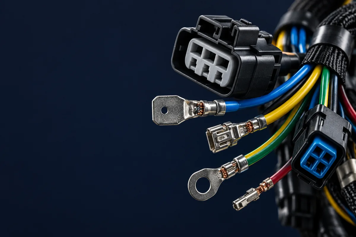
Production-control snapshot: Fine-gauge micro-coaxial assemblies require the factory and customer laboratory to use an aligned impedance definition, fixture, calibration method, limit line, and report format. Without that alignment, launch and adapter variation can be mistaken for cable performance.
A robust release plan checks the customer's impedance definition against the supplier's test method before production approval. That is why this guide treats impedance as a sourcing control, not a catalog label. The body below explains why 50 ohm and 75 ohm coaxial cable behave differently, how connector choice changes the result, and what evidence buyers should request before approving a production lot.
TL;DR
- Use 50 ohm coax for RF power, antennas, instruments, and most wireless links.
- Use 75 ohm coax for video, broadcast, CCTV, CATV, and low-loss receive paths.
- Do not mix 50 ohm and 75 ohm connectors because many still mate mechanically.
- Ask for impedance, VSWR or return-loss, continuity, and shield checks before release.
- For custom assemblies, lock cable family, connector series, bend radius, and test frequency.
Background: Why Buyers Ask This Question
Coaxial cable impedance is the controlled opposition that a coaxial transmission line presents to a high-frequency signal. It is created by the center conductor diameter, dielectric material, shield geometry, and spacing between conductor and shield. A cable can pass continuity and still be wrong if that geometry is not matched to the equipment interface.
This article is written for sourcing engineers, RF-adjacent mechanical engineers, NPI buyers, and supplier-quality teams choosing custom coaxial cable assemblies. Most readers are not designing the radio front end. They are trying to prevent a quote, drawing, or first article from mixing a 50 ohm RF path with a 75 ohm video path, or from pairing a correct cable with the wrong connector body.
Characteristic impedance is a transmission-line property that describes the ratio of voltage to current in a traveling wave. Public references on coaxial cable and characteristic impedance explain the physics, but the factory problem is more practical: the PO must tell the supplier which impedance, cable family, connector family, length, tolerance, and test frequency to build and verify.
50 Ohm vs 75 Ohm: The Practical Difference
A 50 ohm coaxial cable is a coax cable geometry commonly selected for RF power transfer, antennas, wireless modules, lab instruments, GPS, LTE, and many automotive RF links. It balances power handling and attenuation well enough for transmit and receive paths where the equipment port is already designed around 50 ohm.
A 75 ohm coaxial cable is a coax cable geometry commonly selected for video, broadcast, CATV, CCTV, SDI, and broadband-style signal distribution. It often gives lower attenuation for receive or video signal transmission, but it is not a drop-in substitute for a 50 ohm transmitter, antenna, or test port.
The wrong choice creates reflection. Return loss is a measurement of how much signal energy is reflected back toward the source because the cable, connector, or load is mismatched. VSWR is another way to express mismatch on RF lines. Buyers do not need to calculate every value themselves, but they should require the supplier to test the assembly at the relevant frequency range when the application is RF-sensitive.
| Decision Factor | 50 Ohm Coax | 75 Ohm Coax | Buyer Control Point |
|---|---|---|---|
| Typical systems | RF transmitters, antennas, lab instruments, GPS, LTE | CCTV, SDI, broadcast video, CATV, broadband receive paths | Match the equipment port, not available stock |
| Common cable families | RG-58, RG-174, RG-213, LMR-200, LMR-400 | RG-59, RG-6, RG-11, video mini-coax | State exact cable family or approved alternates |
| Connector examples | SMA, TNC, N-Type, 50 ohm BNC, FAKRA | F-Type, 75 ohm BNC, broadcast video connectors | Do not approve connector by appearance only |
| Main performance risk | Reflected power, VSWR drift, transmitter stress | Video reflection, ghosting, link-margin loss, wrong BNC style | Define return-loss or insertion-loss evidence where needed |
| Factory test baseline | Continuity plus VSWR or return loss for sensitive RF paths | Continuity plus impedance or video-path performance checks | Set test frequency, cable length, and acceptance limits |
| Procurement trap | Using cheaper 75 ohm video cable on a 50 ohm RF port | Using 50 ohm BNC parts on a 75 ohm video run | Require cable and connector datasheets with the quote |
Connector Matching Matters as Much as Cable Impedance
Many sourcing failures happen because the cable impedance is correct but the connector is not. A BNC connector is not automatically 50 ohm or 75 ohm just because it mates with the panel jack. The dielectric and center-pin geometry behind the bayonet interface can differ, and the rear ferrule must match the cable OD, braid, dielectric, and center conductor.
For BNC-heavy programs, review the dedicated BNC connector types guide before approving samples. For automotive RF programs, standard FAKRA assemblies are normally 50 ohm, but the buyer still has to lock the key code, cable family, environmental exposure, and RF validation scope. If your assembly is miniaturized, the micro-coaxial cable assembly process needs tighter handling because AWG#40 constructions and 100mm lengths leave little margin for strip-length or fixture mistakes.
Standards language should also be explicit. IPC-A-620 is the inspection framework many buyers use for cable and wire harness workmanship, while UL-758 is often referenced for appliance wiring material traceability. For authority context, use public references for IPC electronics standards and the UL safety organization, then put the exact workmanship, material, and test requirements in your controlled drawing or quality agreement.
Loss, Length, and Frequency Change the Answer
Impedance is only the first gate. Attenuation is the signal loss through the cable, usually shown in dB per 100 ft or dB per 100 m at specific frequencies. The same cable that looks acceptable at 100 MHz may be poor at 2.4 GHz, and a 150mm jumper behaves differently from a 5m enclosure harness.
For production sourcing, ask the supplier to calculate or test the installed length, not just quote a catalog cable. The coaxial cable datasheet guide explains how to read attenuation, velocity factor, bend radius, and shield construction together. If the application is a telecom or antenna feed, the telecommunications cable assembly page gives useful application context for low-loss RF builds.
A practical rule for buyers: when total cable loss approaches 3 dB, half of the signal power is gone before connector loss, adapters, aging, and routing variation are counted. That does not automatically reject the cable, but it does mean the program needs an engineering review instead of a purchasing substitution.
Factory Controls We Use Before Production Release
Specification definition must align with the test method. The drawing should state the nominal impedance and tolerance, frequency range or TDR conditions, reference plane, acceptable fixture and adapters, calibration method, sampling plan, and required report format.
For a normal 50 ohm or 75 ohm coax assembly release, the control plan should include four checks. First, verify the equipment impedance and connector family before quoting. Second, review the cable datasheet for impedance, attenuation at frequency, shield construction, OD, and bend radius. Third, build first articles with controlled strip dimensions and connector-specific tooling. Fourth, define test evidence: continuity for every unit, plus VSWR, return loss, insertion loss, or TDR checks when the application requires them.
RFQ Checklist for 50 Ohm or 75 Ohm Coax Cable Assemblies
- Equipment-side impedance requirement: 50 ohm or 75 ohm.
- Exact cable family, approved alternates, and datasheet revision.
- Connector part numbers, genders, mounting style, and panel details.
- Finished length, tolerance, routing bend radius, and jacket requirement.
- Operating frequency range and maximum allowable insertion loss.
- Required standards or controls such as IPC-A-620 workmanship, UL-758 material evidence, or IATF 16949-style change approval.
- Sample quantity, production quantity, packing method, labels, and test-report format.
Decision Rules for Sourcing Teams
Choose 50 ohm when the system interface is RF power, antenna, transmitter, receiver, GNSS, cellular, Wi-Fi, lab instrumentation, or an automotive RF module designed around 50 ohm. Choose 75 ohm when the interface is video, CCTV, broadcast, SDI, CATV, or a receive/distribution path designed around 75 ohm.
Do not choose by cable diameter, price, color, or the connector name alone. RG-58 and RG-59 may both look like small coax on a BOM, but they usually belong to different impedance families. BNC plugs may mate across impedance families, which is exactly why drawings should call out 50 ohm BNC or 75 ohm BNC rather than just "BNC male."
When the program includes vibration, outdoor routing, repeated flex, or tight packaging, add mechanical controls. Bend radius, boot design, strain relief, and shield termination can change impedance stability even when the nominal cable is correct. For mixed cable harnesses, combine the coax decision with routing and support practices from our wire harness strain relief guide.
Frequently Asked Questions
What is the main difference between 50 ohm and 75 ohm coaxial cable?
50 ohm coax is normally used for RF power transfer, antennas, wireless modules, and lab instruments. 75 ohm coax is normally used for video, CCTV, broadcast, CATV, and broadband-style signal distribution. The difference comes from cable geometry, so the equipment port, connector, and cable must all match.
Can a 50 ohm connector mate with a 75 ohm BNC connector?
Many 50 ohm and 75 ohm BNC connectors can mate mechanically, but that does not make the assembly electrically correct. A mismatched BNC interface can increase reflection and debug time. Buyers should state 50 ohm BNC or 75 ohm BNC on the drawing and confirm the cable range.
Is continuity testing enough for a coaxial cable assembly?
Continuity testing is only the baseline because it confirms the conductors are connected. RF-sensitive assemblies may also need VSWR, return-loss, insertion-loss, impedance, or TDR checks at the application frequency. For a 100mm micro-coax assembly, even fixture alignment can change the measured result.
Which standards should I cite for coax cable assembly quality?
For workmanship, many buyers cite IPC-A-620 because it covers cable and wire harness assembly acceptance criteria. For wire material traceability, UL-758 is often relevant when appliance wiring material is specified. Automotive programs may also require IATF 16949-style change control and customer-specific validation documents.
When should I ask for 100 percent RF testing?
Ask for 100 percent RF testing when the assembly carries an RF path with narrow link margin, high production risk, field-service cost, or a known impedance complaint. For lower-risk video or short internal jumpers, first-article RF testing plus 100 percent continuity may be enough if the customer approves the plan.
What should I send to get a reliable quote?
Send the equipment impedance, cable part number, connector part numbers, finished length, tolerance, operating frequency, bend radius, quantity, standards, and required test report. If the design is not locked, send the application and constraints so the supplier can recommend a 50 ohm or 75 ohm path before sampling.
Final Sourcing Rule
Impedance is a system decision. A supplier can build either 50 ohm or 75 ohm coaxial cable assemblies, but the buyer has to define the application, cable, connector, length, and test requirement before release. If you are unsure which path fits your equipment, send the drawing, datasheet, target frequency, and annual quantity through our contact page. We can review the impedance choice, connector compatibility, and factory test plan before the first article is built.