Real Project Snapshot — Wire Harness Strain Relief Guide
Anonymized example from our case bank, shared so buyers can see how this scope is actually executed in production.
Industry: earthmoving-equipment | Region: Australia | Year: 2023 → 2024
Scenario: An Australian heavy machinery manufacturer requested quotes for multiple custom wire harness models but provided incomplete technical drawings at the initial inquiry stage.
Challenge: Missing critical specifications, including relay models, Deutsch connector models, and Hammond enclosure details, prevented accurate quoting and risked production errors for the 200-piece batch.
Solution: We implemented an engineering-to-engineering clarification process, compiling a detailed technical checklist to guide the client's internal engineering team to provide the missing specs, ensuring all requirements were locked down before sampling.
Result: Achieved full specification lock-down, enabling accurate quoting for 3 sample units and the 200-piece production run, preventing costly rework and material delays.
Concrete numbers: 3 sample units, 200-piece batch size, Deutsch connectors specified, Hammond enclosures specified
Wire Harness Strain Relief: Design Methods, Materials & Selection Guide
Ninety percent of cable assembly failures occur where flexible cable meets a rigid connector. Strain relief controls that transition zone. This guide covers the four primary strain relief methods—overmolding, cable clamps, grommets, and boots—with pull-force data, material comparisons, and selection criteria for automotive, medical, and industrial wire harnesses.
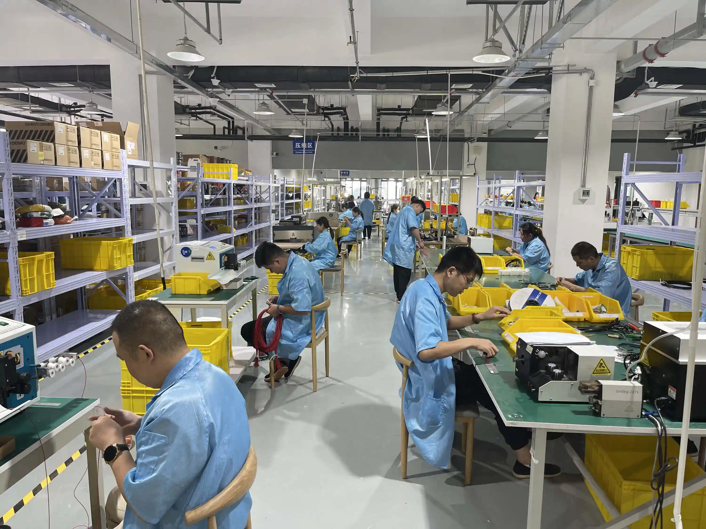
Wire harness assembly line with strain relief application stations
of cable failures occur at the termination point
cable OD for minimum bend radius (static vs. dynamic)
annual failure rate with inadequate strain relief in high-vibration environments
failure rate with properly matched strain relief systems
Table of Contents
- 1. Why Strain Relief Matters in Wire Harness Design
- 2. Four Primary Strain Relief Methods
- 3. Strain Relief Materials: Properties and Trade-offs
- 4. Critical Design Parameters
- 5. Selection Guide by Industry
- 6. IPC-620 Strain Relief Requirements
- 7. Five Strain Relief Mistakes That Cause Field Failures
- 8. Frequently Asked Questions
A wire harness connects two rigid objects—a connector at one end and a device or another connector at the other. Between those endpoints, the cable flexes, bends, and absorbs mechanical loads from vibration, thermal cycling, and human handling. Strain relief manages the transition between rigid and flexible sections. Without it, every pull, twist, or bend concentrates stress directly on solder joints and crimp terminals.
The failure pattern is predictable. Cables pulled from connectors during installation. Wires breaking at the connector backshell after months of vibration. Intermittent connections caused by conductor fatigue at a sharp bend point. These failures account for more warranty returns than any other single cause in cable assemblies shipped without adequate strain relief.
Selecting the right strain relief method requires matching the mechanical environment, production volume, and serviceability requirements. A robotic arm cable that flexes 10 million cycles needs a different solution than a medical device cable that gets sterilized 500 times. This guide covers each method with enough data to specify strain relief confidently on your next wire harness RFQ.
"We see the same mistake on about one in three RFQs: the drawing specifies a connector and wire gauge but says nothing about strain relief. The engineer assumes the manufacturer will figure it out. The manufacturer picks the cheapest zip tie that fits. Six months later, we get a call about field failures. Strain relief needs to be on the drawing from day one, with a pull-force spec and a bend radius callout."
Hommer Zhao
Engineering Director
1. Why Strain Relief Matters in Wire Harness Design
Strain relief transfers mechanical load away from electrical terminations. When someone pulls a cable, the force should be absorbed by the cable jacket and the strain relief mechanism—not by the crimp barrel, solder joint, or PCB pad inside the connector. A properly designed strain relief creates a graduated stiffness transition from the rigid connector housing to the flexible cable body.
The physics are straightforward. Cable flex concentrates stress at the point of maximum curvature change. Without strain relief, that point sits exactly where the cable exits the connector—the weakest spot in the assembly. Individual conductors fatigue and break. Insulation cracks. Shields lose contact. The failure is progressive: intermittent connections appear first, followed by complete open circuits.
Cost of Strain Relief Failures
- Field replacement: $200–$2,000 per incident (labor + downtime + shipping)
- Automotive recall: $50–$500 per vehicle for harness-related electrical failures
- Medical device: $10,000–$100,000+ per FDA adverse event report involving cable failure
- Industrial downtime: $5,000–$50,000 per hour for production line stoppages
Strain relief adds $0.10 to $5.00 per cable assembly depending on the method. Compared to a single field failure, the ROI calculation is obvious. The question is which method to use, not whether to use one.
2. Four Primary Strain Relief Methods
Each method offers different trade-offs in protection level, cost, environmental sealing, and serviceability. Matching the method to your application prevents both under-engineering (field failures) and over-engineering (unnecessary cost).
Overmolded Strain Relief
Injection-molded thermoplastic or elastomer bonded directly around the cable-to-connector junction. The mold creates a smooth, tapered profile that gradually transitions stiffness from the rigid connector to the flexible cable. Multi-durometer designs use a harder material near the connector (Shore 80A–95A) and softer material at the cable end (Shore 35A–55A).
Strengths
- Highest pull-force resistance (50–200+ lbs depending on design)
- Sealed against moisture and dust (IP67/IP68 achievable)
- Smooth exterior prevents snagging; easy to clean
- Repeatable quality in high-volume production
Limitations
- Tooling cost: $2,000–$8,000 per mold cavity
- Not field-serviceable (connector replacement requires cutting)
- Lead time for tooling: 3–6 weeks
- Design changes require new molds
Cable Clamps & Backshells
Metal or plastic clamps that mechanically grip the cable jacket behind the connector. Backshell assemblies thread onto the connector body and cinch down on the cable using a compression nut, saddle clamp, or split-shell design. The cable jacket bears the load instead of the terminations inside.
Strengths
- No tooling cost; off-the-shelf components available
- Field-serviceable (clamp removal allows connector replacement)
- Wide range of sizes for cable ODs from 3 mm to 50 mm+
- Metal versions handle high temperatures and harsh chemicals
Limitations
- Limited environmental sealing without additional gaskets
- Over-tightening can crush cable jacket and damage conductors
- Assembly labor is higher per unit than overmolding at volume
- Can loosen over time under vibration without thread-locking
Grommets & Bushings
Rubber or plastic sleeves with tapered internal passages that compress around the cable jacket when inserted into panel holes or connector bodies. External flanges snap into the mounting hole, while the internal taper distributes strain across the cable jacket length rather than concentrating it at a single point.
Strengths
- Lowest cost per unit ($0.05–$0.50)
- Simple press-fit installation; no tools required
- Provides edge protection for cables passing through metal panels
- Available in thousands of standard sizes
Limitations
- Low pull-force resistance (3–15 lbs typical)
- No graduated stiffness transition; sharp bend point at grommet edge
- Limited IP rating without secondary sealing
- Rubber compounds degrade under UV and ozone exposure
Flexible Boots & Heat-Shrink Transitions
Pre-formed elastomer boots that slide over the cable-connector junction, or dual-wall heat-shrink tubing with adhesive lining that conforms to irregular shapes when heated. Segmented boot designs with ribbed sections allow controlled bending while restricting the minimum bend radius.
Strengths
- Good graduated stiffness transition (especially segmented designs)
- Moderate cost ($0.50–$5.00 per unit)
- Heat-shrink versions seal against moisture (IP65–IP67)
- No tooling; works with any connector shape
Limitations
- Pull-force limited to jacket-to-boot friction (10–40 lbs)
- Heat-shrink is permanent; not field-serviceable
- Boot sizing must match cable OD closely (limited flexibility)
- Standard heat-shrink creates a stiff section that can shift the stress point
"A zip tie cinched tight behind a connector is not strain relief. It concentrates force on a 2-millimeter line across the cable jacket. Within a few hundred flex cycles, that zip tie edge cuts through the jacket and starts abrading the conductors underneath. We reject any incoming design that uses a zip tie as the primary strain relief method."
Hommer Zhao
Engineering Director
3. Strain Relief Materials: Properties and Trade-offs
Material selection determines temperature range, chemical resistance, flex life, and cost. The wrong material fails even when the mechanical design is sound.
| Material | Temp Range | Shore Hardness | Chemical Resistance | Best For | Cost |
|---|---|---|---|---|---|
| PVC | -20°C to +80°C | 60A–90A | Moderate | Consumer, general industrial | $ |
| TPE | -40°C to +120°C | 35A–95A | Good | Automotive, industrial | $$ |
| TPU | -40°C to +100°C | 70A–95A | Excellent (oils, fuels) | Automotive, robotics | $$ |
| Silicone | -60°C to +200°C | 20A–80A | Good (autoclave safe) | Medical, aerospace | $$$ |
| Nylon (PA6/PA66) | -40°C to +120°C | Rigid (75D+) | Good | Clamps, backshells, grommets | $ |
| Stainless Steel | -200°C to +800°C | Rigid (metal) | Excellent | Aerospace, military, marine | $$$$ |
Material Selection Rule of Thumb
Match the strain relief material to the cable jacket material whenever possible. PVC cable + PVC strain relief. TPU cable + TPU overmold. Matching materials ensures the overmold bonds chemically to the jacket, increasing pull-force resistance by 30–50% compared to mechanical grip alone. If materials must differ, use a primer or adhesion promoter during molding.
4. Critical Design Parameters
Minimum Bend Radius
The tightest radius a cable can follow without mechanical damage. Strain relief must enforce this radius mechanically.
- Static (fixed routing): 5x cable outer diameter minimum
- Dynamic (continuous motion): 10x cable outer diameter minimum
- High-flex robotics: 7.5x with high-flex rated conductors and jacket
Pull-Force Requirements
Based on IPC/WHMA-A-620 minimum values and common industry additions:
| Wire Gauge | IPC Minimum | Automotive Typical | Medical Typical |
|---|---|---|---|
| 28 AWG | 2 lbs (0.9 kg) | 4 lbs (1.8 kg) | 15 lbs (6.8 kg) |
| 22 AWG | 5 lbs (2.3 kg) | 10 lbs (4.5 kg) | 15 lbs (6.8 kg) |
| 18 AWG | 10 lbs (4.5 kg) | 20 lbs (9.1 kg) | 20 lbs (9.1 kg) |
| 14 AWG | 20 lbs (9.1 kg) | 40 lbs (18.1 kg) | 30 lbs (13.6 kg) |
Stiffness Transition Ratio
The ideal strain relief tapers from connector stiffness to cable stiffness over a distance of 3–5x the cable diameter. Overmolded designs achieve this through graduated durometer zones. A 3:1 maximum stiffness change ratio at any point along the transition prevents stress concentration. Exceeding 3:1 moves the failure point from the connector junction to the end of the strain relief—solving nothing.
5. Selection Guide by Industry
Automotive
Vibration is the primary enemy. Engine compartment harnesses endure continuous vibration at 5–2,000 Hz for the vehicle's entire life. Underbody harnesses add salt spray, road debris, and temperature extremes (-40°C to +125°C).
Recommended: Overmolded TPE for sealed connections. Nylon cable clamps with rubber inserts for routed harness sections. Backshell assemblies on high-voltage EV connectors. All strain relief must survive 10+ million vibration cycles per automotive OEM qualification tests (LV 214, GMW 3172).
Medical Devices
Sterilization compatibility drives material selection. Reusable cables must survive 500+ autoclave cycles at 134°C without cracking or losing bond strength. Patient-connected cables need biocompatible materials meeting ISO 10993.
Recommended: Silicone overmolding for patient-contact cables. Medical-grade TPE for instrument cables. Sealed boot designs for single-use disposable assemblies where tooling cost must be low. Pull-force testing per IEC 60601-1 requirements (15 lbs minimum).
Industrial Automation & Robotics
Continuous-motion applications demand the highest flex life. Robot arm cables bend millions of times over their service life, while drag chain cables endure continuous lateral bending with added tensile load.
Recommended: Segmented boots with TPU material for robotic joints (10M+ flex cycles). Stainless steel cable clamps for panel entries in washdown environments. Overmolded TPU for drag chain cable ends. Avoid PVC—it cracks after 50,000–100,000 flex cycles in dynamic applications.
Aerospace & Military
Weight is critical, and specifications are non-negotiable. MIL-DTL-38999 and MIL-DTL-26482 connectors have standardized backshell interfaces for strain relief. All materials must pass outgassing tests (ASTM E595) for space applications.
Recommended: Metal backshells with EMI termination for shielded aerospace harnesses. Segmented silicone boots for non-shielded runs. Every strain relief point documented on the harness drawing with torque values and inspection criteria per AS9100.
6. IPC-620 Strain Relief Requirements
IPC/WHMA-A-620 is the primary workmanship standard for cable and wire harness assemblies. It defines three product classes with escalating strain relief requirements.
| Requirement | Class 1 (General) | Class 2 (Service) | Class 3 (High-Reliability) |
|---|---|---|---|
| Strain relief required? | Where specified | All termination points | All termination points + routing |
| Bend radius control | Visual check | Per drawing spec | Measured and documented |
| Pull-force testing | Not required | First article | First article + periodic |
| Inspection | Sampling | Sampling per AQL | 100% inspection |
| Redundant strain relief | Not required | Not required | Required on critical circuits |
7. Five Strain Relief Mistakes That Cause Field Failures
1. Using Zip Ties as Primary Strain Relief
A cable tie cinched directly behind a connector creates a sharp pressure ridge. Vibration causes the tie edge to abrade through the jacket within weeks. The conductor insulation follows. Use zip ties for bundle management, not strain relief.
2. Ignoring Stiffness Transition
Standard heat-shrink tubing applied over a connector junction makes the cable rigid for 20–40 mm, then transitions abruptly to full flexibility. This moves the stress concentration from the connector to the end of the heat-shrink. Use adhesive-lined heat-shrink with graduated wall thickness, or a flexible boot with a tapered profile.
3. Mismatched Materials
Overmolding PVC onto a TPU cable jacket produces a weak bond. The overmold separates from the jacket under thermal cycling, leaving a gap that lets moisture in and reduces pull-force by 60–80%. Matched or chemically compatible materials are essential for overmolded designs.
4. Specifying Pull-Force Without Test Method
"50 lbs pull-force" means different things depending on the test. Axial pull at 50 mm/min along the cable axis differs from a 45-degree angled pull or a jerk test. Specify the test standard (IPC-620, UL 486A, or customer-specific), pull direction, speed, hold time, and pass/fail criteria.
5. No Strain Relief on the Drawing
When strain relief is not specified on the harness drawing, the manufacturer makes the cheapest choice that passes visual inspection. The result works on the bench and fails in the field. Call out the strain relief method, material, pull-force spec, and bend radius on the engineering drawing or in the RFQ specification.
"We prototype every new overmolded strain relief design using 3D-printed molds before cutting steel. A printed TPU mold costs $50 and takes 4 hours. It catches 90% of design problems—short shots, flash, poor gate location—before you commit $5,000 to production tooling. The savings on failed first-shots alone pay for the 3D printer."
Hommer Zhao
Engineering Director
8. Frequently Asked Questions
What is strain relief in a wire harness?
Strain relief is a mechanical protection system that secures cables at their entry and exit points from connectors, enclosures, or junction boxes. It prevents pulling, bending, and twisting forces from transferring to solder joints, crimp terminals, or wire terminations. Methods include overmolded boots, cable clamps, grommets, and backshell assemblies.
What minimum bend radius should I specify for strain relief?
For static installations, specify 5x the cable outer diameter. For dynamic applications with continuous or repeated motion (robotics, drag chains), specify 10x the cable outer diameter. Tighter radii accelerate conductor fatigue and insulation cracking. High-flex cables with stranded conductors can use 7.5x in dynamic applications.
How do I choose between overmolded and mechanical strain relief?
Choose overmolding when production volume exceeds 1,000 units, IP67+ sealing is required, or pull-force needs exceed 50 lbs. Choose mechanical strain relief (clamps, backshells) for low volumes, prototyping, or applications requiring field serviceability. For mid-range volumes (200–1,000 units), flexible boots with adhesive heat-shrink offer a cost-effective middle ground.
What pull-force rating should strain relief meet?
IPC/WHMA-A-620 specifies minimums based on wire gauge (2 lbs for 28 AWG to 20 lbs for 14 AWG). Automotive OEMs require 1.5–2x IPC minimums. Medical devices typically specify 15 lbs minimum regardless of gauge per IEC 60601-1. Always specify the test method alongside the force value.
Does IPC-620 cover strain relief?
Yes. IPC/WHMA-A-620 addresses strain relief under cable retention and mechanical protection. Class 1 requires basic strain relief where specified. Class 2 adds controlled bend radius and retention force requirements at all termination points. Class 3 demands redundant strain relief, 100% inspection, and documented pull-force testing.
References & External Resources
Need Wire Harnesses with Engineered Strain Relief?
Our manufacturing team designs and produces wire harnesses with overmolded, clamped, and booted strain relief for automotive, medical, industrial, and aerospace applications. Get a quote with pull-force specifications within 48 hours.