Robotics and Motion Equipment
Sensor, motor, encoder, EOAT, and camera cables where repeated flex can load the connector exit, shield drain, or branch breakout.
Cable Assembly
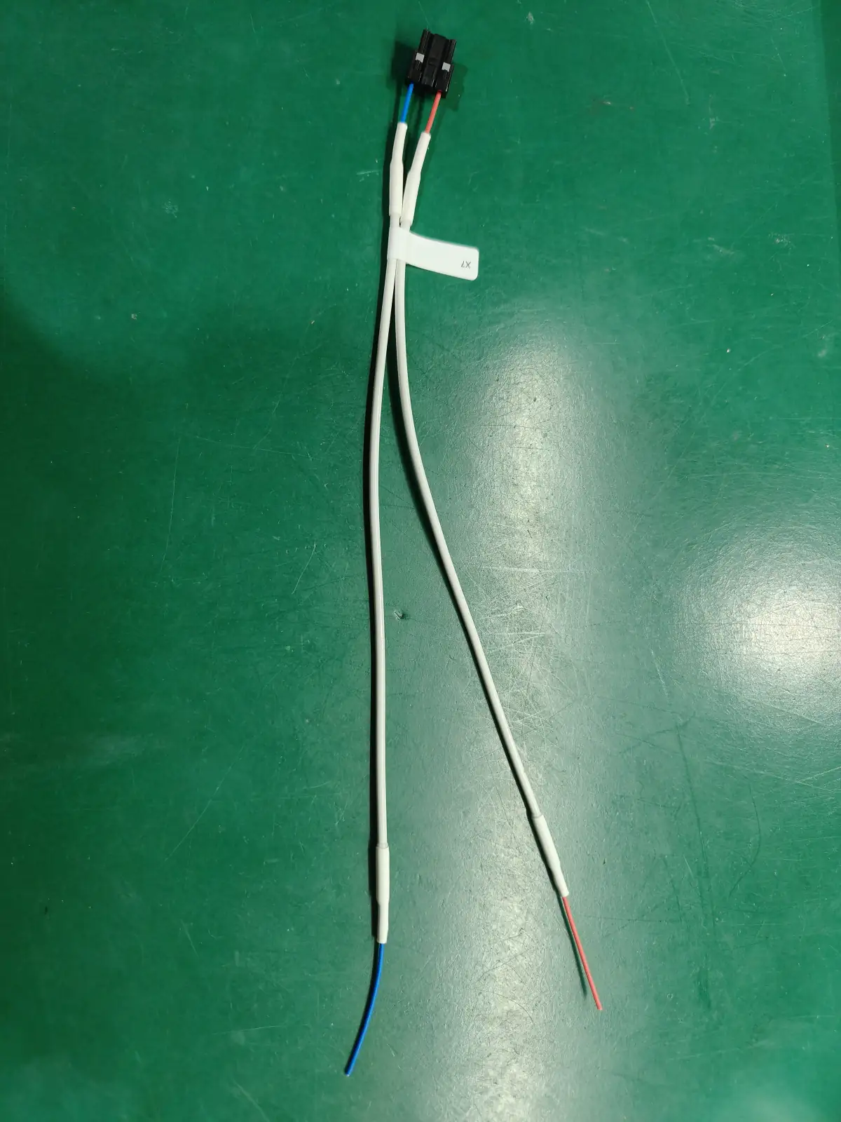
A strain relief cable assembly is a wire harness or cable assembly built so cable movement, pull force, bend stress, and vibration do not load the crimp, solder cup, seal, or connector contact. We review cable OD, wire gauge, connector exit, bend radius, boot geometry, heat-shrink stack, gland compression, overmold option, and test evidence before quote.
Application Context
A strain relief cable assembly is a wire harness or cable build made so cable movement, pull force, bend stress, and vibration do not load the crimp, solder cup, seal, or connector contact. The useful work is not picking the strongest boot — it is reviewing cable OD, wire gauge, connector exit, bend radius, boot geometry, heat-shrink stack, gland compression, and the overmold option against the real cable route so the protection method matches the weak point without blocking assembly, service, or test.
The right method depends on the failure mode. When repeat handling, sealing, cosmetics, or controlled bend geometry justify tooling cost, an overmolded cable assembly distributes flex and pull stress around the exit; when quantities are low or the drawing may still change, heat-shrink tubing and assembled boots are faster and easier to service. Elevated-temperature exits pair with a high-temperature cable assembly review, and panel-mounted or enclosure builds are released together with box build cable assembly so strain relief, mounting, labels, and final test are locked as one revision.
TL;DR
Applications
This service is most useful when the cable is handled, moved, pulled, wiped down, routed through a panel, or exposed to vibration after installation.
Sensor, motor, encoder, EOAT, and camera cables where repeated flex can load the connector exit, shield drain, or branch breakout.
Reusable or field-handled cable assemblies where wipe-down, bend stress, and repeated plugging cycles must be considered before release.
Panel-entry cables, operator stations, pump leads, control boxes, and machine modules with glands, clamps, boots, or service loops.
Cable exits that need mechanical support together with IP-rated connectors, adhesive heat shrink, grommets, or overmolded sealing.
Automotive, EV, motorcycle, marine, and off-highway harness branches where vibration, clips, conduit, and bend radius drive the protection stack.
Prototype and pilot cables where buyers need to compare overmold tooling against faster boot, sleeve, heat shrink, or clamp options.
Engineering Challenges
Repeated bending, pull force, and vibration load the terminal, latch, shield drain, and jacket edge at the connector exit. The stress the cable will actually see is confirmed before a gland, boot, clamp, heat shrink, sleeve, or overmold is selected.
Where a cable enters a panel, enclosure, or machine body, gland size, thread, jacket, torque, and IP target must match the route. The installation and sealing scope is separated from the cable test scope so neither is assumed.
Strain relief applied too early can hide a weak crimp, poor connector seating, or bad wire dress. The inspection sequence defines when crimp, seating, sleeve recovery, label, and electrical checks happen before the transition is covered.
Overmolding improves repeat handling and sealing but adds tooling cost and lead time. Tooling, MOQ, material substitution, and serviceability are made visible as assumptions instead of surfacing after the sample PO.
Technical Capabilities
Strain relief options, RFQ inputs, sample targets, test scope, cable types, and quality references for a strain relief cable assembly program.
Manufacturing Process
Quality & Testing
Every strain relief cable assembly is checked against the failure mode named in the RFQ — continuity, polarity, pull-force review, connector seating, and visual inspection are done before the boot, sleeve, gland, or overmold hides the termination, with hi-pot or insulation resistance (via a qualified third party) added where voltage and construction justify it, and records tied to the released drawing revision.
Why WHP
A senior factory engineer reviews the mechanical path, electrical risk, and buying constraint together instead of quoting a generic boot or sleeve.
Pull force, repeated bending, vibration, sealing compression, shield damage, and service handling create different risks. We ask which stress the cable will see before selecting a gland, boot, clamp, heat shrink, sleeve, or overmold.
Overmolding can improve repeat handling and sealing, but it adds tooling cost and lead time. Heat shrink, assembled boots, or clamps can be better when the drawing may change during validation or the production quantity is still uncertain.
Strain relief can hide bad workmanship if it is applied too early. Our work instructions define when crimp inspection, connector seating, sleeve recovery, label checks, and electrical test happen in the sequence.
The approved drawing, wire list, connector kit, strain relief material, shrink setting, test method, and packaging note are linked to the same revision so receiving teams can audit repeat orders.
Strain relief review combines wire-harness workmanship, wire material context, and quality-system document control, referenced so buyers can align terminology during supplier qualification.
FAQ
OEM Program Entry
Send your drawing, connector references, cable OD, route photos, bend direction, target quantity, and test needs. We will review the weak point, compare protection options, and return a quote with sample timing and release evidence.
Related Capabilities
Use these pages when strain relief also depends on heat, shielding, or release testing.
Capabilities
The strongest strain relief is not always the most expensive one. It is the option that protects the weak point without blocking assembly, service, or test.
A connector exit is the transition area where the cable leaves the connector, backshell, gland, boot, or overmold. We check whether motion will load the terminal, latch, seal, shield termination, or jacket edge before deciding the strain relief method.
A heat-shrink boot is a recovered tubing or molded-shape component used to support the cable exit and cover the transition. We control shrink ratio, adhesive flow, sleeve overlap, recovery temperature, and inspection points so the boot does not hide a weak termination.
A cable gland is a compression fitting that supports and seals a cable where it enters a panel, enclosure, or machine body. We match gland size, thread, cable jacket, torque expectation, and service access with the finished harness assembly.
An overmolded strain relief is an injection-molded polymer transition that distributes flex and pull stress around the cable exit. We recommend it when durability, sealing, cosmetics, or repeat handling justify tooling cost; for low-volume validation, heat shrink or assembled boots can be faster.
Representative Project
Representative project type we handle, shown for illustration. Not a specific named customer.
A buyer brings a Strain Relief Cable Assembly program where impedance and signal integrity must be held tightly across every unit.
Signal-sensitive assemblies can fail in production when the cable target, test method, and acceptance record are not aligned before release — a specification-versus-test mismatch, not a simple operator error.
We align the cable specification, test method, and acceptance record up front, qualify samples against that agreed method, and lock the release record before volume build.
Defining the target, test method, and acceptance criteria before release keeps signal-sensitive programs out of the costly rework loop that a late spec/test mismatch creates.
Working Together
These answers address the details that usually change price, sample timing, and field reliability.
References
Buyer review usually combines workmanship, wire material, quality-system, and general cable-harness references with the connector manufacturer's own documentation.
Reviewed By
Wire harness and cable assembly manufacturing specialist at WHP