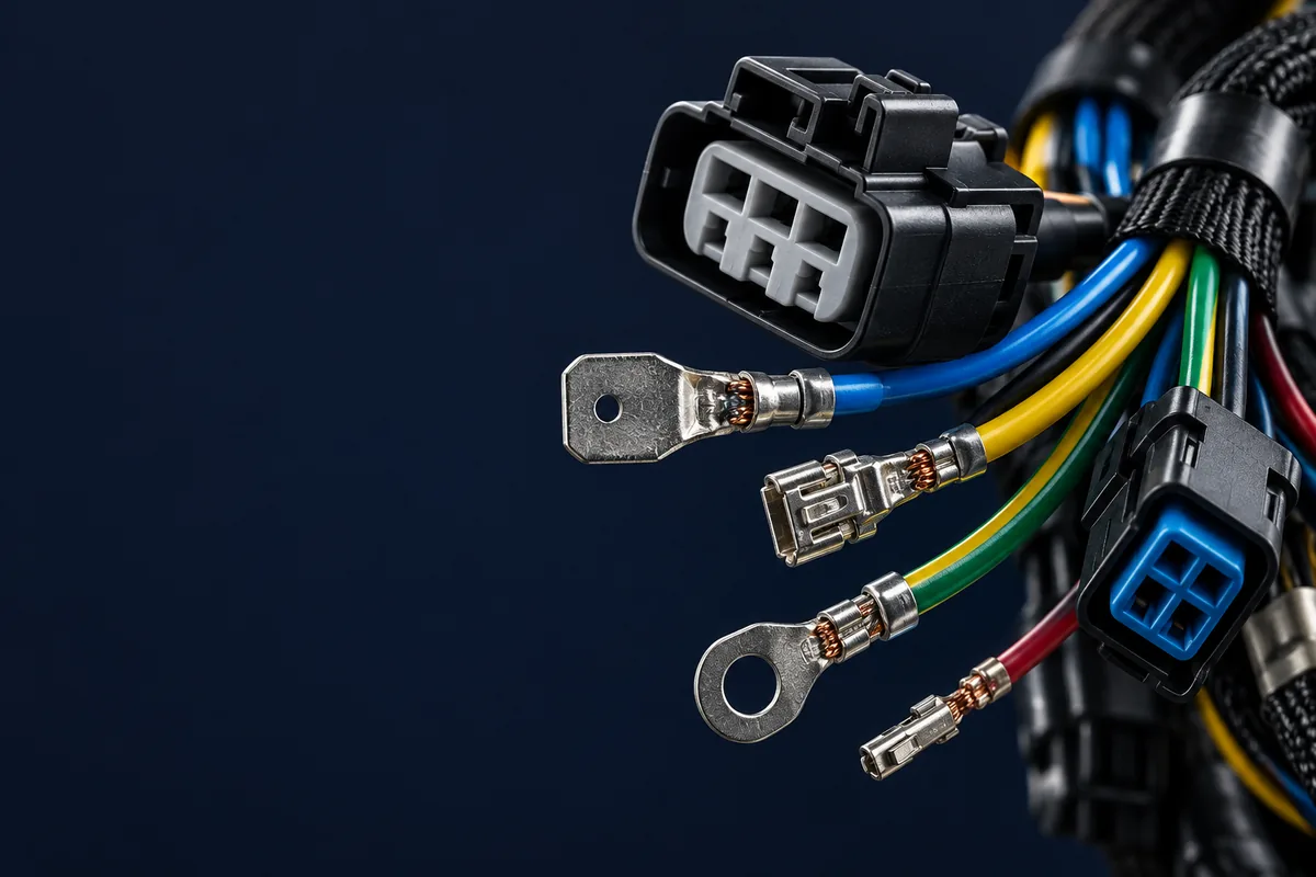
A comprehensive guide to help engineers and procurement teams decide between custom and standard coaxial cable assemblies—covering cable types, connector options, impedance matching, and cost-benefit analysis.
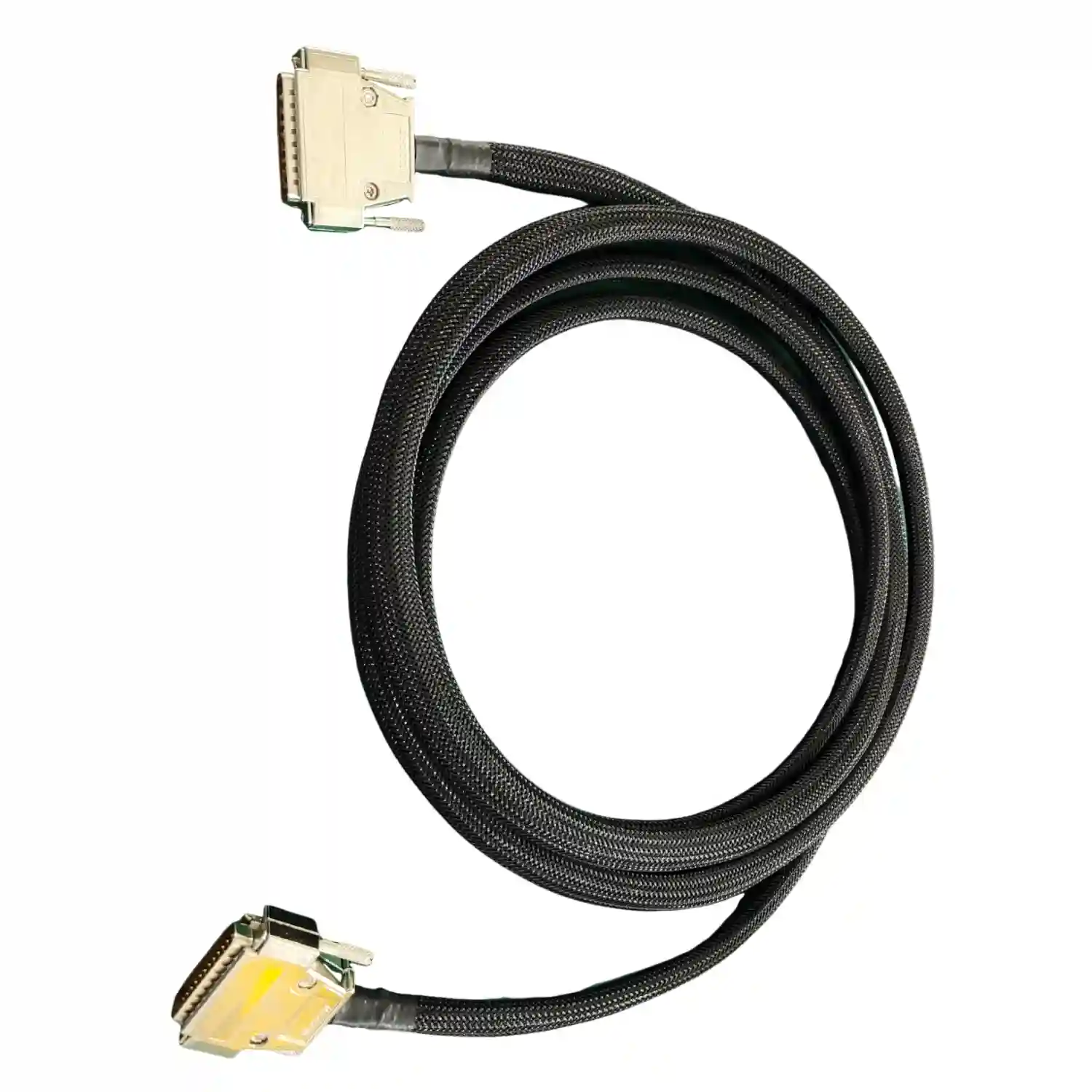
1. What is a Coaxial Cable Assembly?
A coaxial cable assembly consists of a coaxial cable terminated with connectors at one or both ends, ready for immediate installation. The term "coaxial" refers to the cable's construction: a central conductor surrounded by insulation, a metallic shield, and an outer jacket—all sharing a common geometric axis.
Coaxial cables are designed to transmit high-frequency electrical signals with minimal interference. Unlike standard wire harnesses that simply conduct electricity, coaxial assemblies maintain signal integrity through their controlled impedance design—a critical factor for RF, video, and data transmission applications.
Key Components of a Coaxial Cable:
- Center Conductor: Solid or stranded copper/copper-clad steel carrying the signal
- Dielectric Insulation: PE, PTFE, or foam separating conductor from shield
- Metallic Shield: Braided copper, foil, or combination for EMI protection
- Outer Jacket: PVC, PE, or LSZH protection against physical damage
Coaxial cable assemblies support telecommunications, industrial equipment, industrial instrumentation, and medical device applications. Custom assemblies address application-specific routing, connection, and test requirements.
2. Understanding Coaxial Cable Types
RG designations identify familiar coaxial cable families. Common commercial and industrial choices include RG58, RG59, RG6, RG11, and RG213/214; verify the exact manufacturer construction before selection.
If your program is really trying to solve distance, EMI isolation, or high-density patching rather than RF power transfer, copper coax may not be the right architecture at all. In those cases our optical cable assembly service is the better fit for fiber-based interconnect builds that need polarity control, connector protection, and insertion-loss testing.
| Cable Type | Impedance | OD (mm) | Frequency | Primary Applications |
|---|---|---|---|---|
| RG58 | 50Ω | See part datasheet | Part-specific | RF communications, ham radio, test equipment |
| RG59 | 75Ω | See part datasheet | Part-specific | CCTV, analog video, short-run broadcast |
| RG6 | 75Ω | See part datasheet | Part-specific | CATV, satellite, digital video |
| RG11 | 75Ω | See part datasheet | Part-specific | Long-distance CATV, trunk lines |
| RG174 | 50Ω | See part datasheet | Part-specific | GPS, WiFi antennas, space-constrained applications |
| RG213/214 | 50Ω | See part datasheet | Part-specific | High-power RF, industrial, broadcast |
| LMR-400 | 50Ω | 10.29 (nominal) Times Microwave | Check the selected part rating | Cellular base stations, low-loss applications |
RG58 vs RG59: Don't Confuse Them!
Despite similar names, RG58 (50Ω) and RG59 (75Ω) are intended for different system impedances. Using the wrong impedance cable can cause reflections and reduce delivered power. Always verify impedance requirements before specifying cable type.
Attenuation Comparison
Signal attenuation (loss) increases with frequency and cable length. This is particularly critical when selecting cable for long runs or high-frequency applications:
| Cable Type | @ 100 MHz | @ 400 MHz | @ 1 GHz | @ 2.4 GHz |
|---|---|---|---|---|
| RG58 | See part datasheet | See part datasheet | See part datasheet | See part datasheet |
| RG6 | See part datasheet | See part datasheet | See part datasheet | See part datasheet |
| LMR-400 | See part datasheet | See part datasheet | See part datasheet | See part datasheet |
RG vs LMR: Pick the Family First
The fastest way to land on a coax type is to choose the family before the number. Most of what you will specify is either a legacy RG cable or a low-loss LMR® cable, and each has a different selection rule.
Legacy "RG" labels alone do not specify every construction detail. Cables carrying the same RG designation can differ in shield coverage, dielectric, and loss. For critical applications, specify the manufacturer part number and controlled construction.
The LMR low-loss family uses a bonded aluminium-foil-plus-braid shield over a foam dielectric. It trades flexibility for markedly lower attenuation, making it an option for outdoor antenna feedlines and runs where the loss budget over distance — not connector choice — is what limits the design. When a build needs that low-loss backbone terminated and tested, it becomes an RF cable assembly rather than an off-the-shelf jumper.
LMR Low-Loss Series — Selection Table
The standard LMR models listed below are 50Ω; other LMR variants can have a different impedance. Diameter, bend radius, and loss must be assessed together. The nominal dimensions and attenuation at 2500 MHz below are from the Times Microwave LMR guide; confirm the exact variant and datasheet revision before ordering.
| Cable Type | Nominal OD | Velocity (VoP) | Attenuation @ 2500 MHz | Typical Use |
|---|---|---|---|---|
| LMR-195 | 4.95 mm (0.195") | 80% | 19.0 dB/100 ft Source | Short jumpers, GPS/GNSS and Wi-Fi antenna leads, tight routing |
| LMR-240 | 6.10 mm (0.240") | Check variant datasheet | 12.9 dB/100 ft Source | Mid-length jumpers, in-cabinet RF, antenna drop cables |
| LMR-400 | 10.29 mm (0.405") | Check variant datasheet | 6.8 dB/100 ft Source | Antenna feedlines, cellular/ISM base runs, low-loss backbone |
| LMR-600 | 14.99 mm (0.590") | Check variant datasheet | 4.4 dB/100 ft Source | Long feedlines, tower runs, low-loss fixed installations |
Compare loss at the same frequency and installed length using the selected cable datasheets. A lower-loss construction may preserve more link margin on a long antenna run.
Which family should you specify?
- Choose LMR when the run is long, outdoors, or feeding an antenna and every dB of loss costs you range or link margin — feedlines, tower drops, rooftop-to-radio, low-loss ISM and cellular backbones.
- Choose RG when you need flexibility and a tight bend radius, the run is short and indoors, cost per foot matters, or you are matching legacy equipment — patch leads, bench jumpers, in-box video on RG59/RG6, instrumentation on RG174/RG316.
- Budget for the bend-radius cost. The standard LMR-600 has a 38.1 mm minimum installation bend radius in the Times Microwave LMR guide. Repeated bending has a different limit. If the assembly has to flex, cross a hinge, or fit a crowded enclosure, a smaller LMR (195/240) or a flexible RG type is the practical pick even at higher loss.
3. Custom vs Off-the-Shelf: Key Differences
The decision between custom and off-the-shelf (OTS) coaxial cable assemblies affects your project's cost, lead time, and performance. Understanding the trade-offs helps make the right choice for your application.
Custom Coaxial Assemblies
- Exact lengths—no excess cable to manage
- Application-specific connector combinations
- Enhanced shielding options available
- Custom labeling and color coding
- Test reports and traceability
- Specialty jacket materials (PTFE, silicone)
Lead time: Confirm material availability and production schedule
MOQ: Confirm with the supplier
Off-the-Shelf Assemblies
- Stock availability depends on configuration
- Lower unit cost for standard configs
- Order quantity depends on supplier policy
- Quality depends on the approved product and supplier
- Easy replacement and spare parts
- Multiple supplier options
Lead time: Confirm stock and dispatch timing
MOQ: Confirm order policy
4. When to Choose Custom Coaxial Assemblies
Custom coaxial cable assemblies are particularly valuable for applications where standard solutions fall short. Here are the scenarios where custom makes the most sense:
1. Industrial Applications
Industrial systems may require cables that perform across a customer-specified temperature range, withstand vibration, and meet controlled-impedance requirements. Semi-rigid coaxial cables can be formed to drawing-defined bend configurations for RF test systems, instrumentation, and broadband equipment.
2. Medical Device Integration
Medical wire harness manufacturers often produce custom coaxial assemblies for ultrasound probes, patient monitoring, and diagnostic imaging. Requirements for biocompatibility, impedance control, and assembly environment depend on the device and its intended use.
3. Tight Space Constraints
When equipment enclosures don't allow for standard cable lengths or bend radii, custom assemblies solve the problem. Right-angle connectors, specific jacket colors for identification, and exact-length cables eliminate routing challenges.
4. Repeat Production Quantities
Custom assemblies may become economical when setup costs are spread across repeat orders and exact-fit routing reduces installation work. Compare actual quotes and labor assumptions.
5. Harsh Environment Requirements
Applications exposed to UV, chemicals, extreme temperatures, or continuous flexing need specialized materials. Custom assemblies can specify PTFE dielectrics, double-shielded construction, and outdoor-rated jackets when standard products do not meet the requirement.
5. When Off-the-Shelf Solutions Make Sense
Off-the-shelf coaxial assemblies can suit standard applications. Check a supplier's current catalog, availability, and test documentation for the required configuration.
Ideal Scenarios for Off-the-Shelf:
- Prototype development and testing
- Laboratory test setups
- Maintenance and replacement needs
- Standard CCTV installations
- Consumer electronics integration
- Low-volume production
- Urgent project timelines
- Standard home/office networking
Many organizations use a hybrid approach: off-the-shelf for prototypes and R&D, then transition to custom assemblies for production. This balances speed-to-market with cost optimization. See our guide on custom cable assembly process for transitioning from prototype to production.
6. Connector Types for Coaxial Cables
50Ω RF Connectors (Signal Transmission)
| Connector | Frequency | Coupling | Best For |
|---|---|---|---|
| BNC (50Ω) | Check exact part rating | Bayonet | Test equipment, oscilloscopes, radio |
| TNC | Check exact part rating | Threaded | Vibration environments, cellular |
| N-Type | Check exact part rating | Threaded | High power, base stations, weatherproof |
| SMA | Check exact part rating | Threaded | Microwave, GPS, WiFi antennas |
| SMB | Check exact part rating | Snap-on | Telecommunications, automotive |
| MCX | Check exact part rating | Snap-on | Space-constrained, GPS, cellular |
75Ω Video Connectors
| Connector | Frequency | Coupling | Best For |
|---|---|---|---|
| F-Type | Check exact part rating | Threaded | CATV, satellite, home installations |
| BNC (75Ω) | Check exact part rating | Bayonet | Broadcast video, CCTV, SDI |
| RCA | Check exact part rating | Push-on | Consumer audio/video |
Connector Mating Cycles
Mating-cycle ratings depend on the specific connector, contact finish, and test conditions. For frequent connections, check the manufacturer's durability rating and application limits.
7. Impedance Matching: 50Ω vs 75Ω
Understanding impedance is fundamental to coaxial cable selection. Using mismatched impedance causes signal reflection, standing wave ratio (SWR) problems, and potential equipment damage.
50 Ohm Coaxial
Optimized for power transmission with balanced compromise between signal attenuation and power handling.
Common Applications:
- Two-way radio and ham radio
- Cellular base stations
- Test and measurement equipment
- WiFi and GPS antennas
- RF and microwave test systems
Cable Types: RG58, RG174, RG213, LMR-400
Connectors: BNC, TNC, N-Type, SMA
75 Ohm Coaxial
Commonly used for video distribution where the system is designed around this impedance.
Common Applications:
- CCTV and security systems
- Cable television (CATV)
- Satellite TV receivers
- Broadcast video and SDI
- Digital signage
Cable Types: RG59, RG6, RG11
Connectors: F-Type, BNC (75Ω)
8. Critical Specifications for Selection
Beyond impedance, several specifications determine whether a coaxial cable assembly will perform in your application. Here's what to evaluate:
Attenuation (Signal Loss)
Measured in dB per unit length at specific frequencies. Lower is better. Attenuation increases with frequency and cable length. For long runs or high-frequency applications, choose low-loss cables like LMR-400 over RG58.
Selection rule: Compare total path loss with the system link budget before choosing a cable or amplifier.
Velocity of Propagation (VoP)
The speed of signal travel through the cable expressed as a percentage of the speed of light. Important for timing-critical applications and cable length calculations.
Selection rule: Use the specified cable's velocity factor for delay and electrical-length calculations.
Shielding Effectiveness
Shielding depends on shield construction, coverage, frequency, and termination. Check the selected cable's coverage and shielding specifications for the intended interference environment.
For industrial environments: Specify double-shielded cables where the interference assessment supports that choice.
Minimum Bend Radius
The tightest bend the cable can make without performance degradation. Bending tighter than the specified minimum radius can change impedance and increase VSWR. Use the selected cable's installation and repeated-flex bend limits.
Temperature Rating
Temperature limits depend on the complete cable construction, including dielectric and jacket. Check the manufacturer rating for the intended environment.
Power Handling
Maximum RF power the cable can handle without overheating. Larger diameter cables handle more power. Critical for transmitter applications—apply the manufacturer's frequency, ambient-temperature, and duty-cycle limits.
Coaxial Cable Selection Checklist
- Impedance (50Ω or 75Ω)
- Operating frequency range
- Total cable run length
- Maximum acceptable attenuation
- Connector types both ends
- Environmental conditions
- Temperature range
- Flex/bend requirements
- Shielding requirements
- Industry certifications needed
9. Cost Analysis and ROI
The true cost of coaxial cable assemblies extends beyond the purchase price. Understanding total cost of ownership helps justify custom vs. off-the-shelf decisions.
| Cost Factor | Off-the-Shelf | Custom |
|---|---|---|
| Unit Price | Quote required | Quote required |
| Setup/NRE Cost | Confirm with supplier | Confirm with supplier |
| Installation Labor | Higher (excess cable) | Lower (exact fit) |
| Lead Time | Confirm stock and transit | Confirm materials and production |
| Documentation | Generic datasheet | Custom test reports |
| Warranty Support | Standard | Application-specific |
Cost Comparison Inputs
Scenario: Compare standard and custom cables for the same test-equipment build.
Off-the-Shelf Approach:
- • Quoted standard cable price × required quantity
- • Installation time measured on the proposed routing
- • Installation hours × applicable labor rate
- • Total: cable, installation, and delivery costs
Custom Approach:
- • Quoted custom cable price × required quantity
- • Quoted setup and engineering charges
- • Installation time measured on the custom routing
- • Installation hours × applicable labor rate
- • Total: cable, setup, installation, and delivery costs
The economical choice depends on the quoted prices, installation work, and order volume. A higher volume does not by itself guarantee that custom assemblies become cheaper.
10. Working with Custom Coaxial Manufacturers
Getting successful custom coaxial cable assemblies requires clear communication with your manufacturer. Here's how to ensure smooth collaboration:
Information to Provide for Custom Quotes
-
1
Cable type and impedance (e.g., RG58, 50Ω) or specify if you need recommendations
-
2
Connector types for each end (e.g., BNC male to SMA male)
-
3
Overall length and tolerance (define the permitted tolerance on the drawing)
-
4
Operating frequency range and maximum attenuation acceptable
-
5
Environmental requirements (temperature, outdoor use, chemical exposure)
-
6
Testing requirements (continuity, VSWR, insertion loss, hipot)
-
7
Standards and records needed (UL, RoHS, customer-specified requirements, etc.)
-
8
Quantity and delivery schedule
For detailed guidance on submitting RFQs, see our Wire Harness RFQ Checklist. The principles apply equally to coaxial cable assemblies.
When evaluating manufacturers, look for those with experience in your specific industry. See our guide on how to choose a wire harness manufacturer for comprehensive evaluation criteria.
Illustrative production-control scenario
Hypothetical example of translating impedance requirements into a repeatable test plan.
Application: fine-gauge micro-coaxial assemblies | Stage: pilot and production release
Scenario: A fine-gauge micro-coaxial assembly requires impedance evidence that can be reproduced by both the factory and the customer laboratory.
Challenge: Short assemblies are sensitive to fixture launches, adapters, calibration, cable routing, and the way acceptance limits are reported.
Solution: Align the drawing, impedance definition, fixture, calibration method, limit lines, sampling plan, and report format before approving the production test method.
Intended outcome: Comparable test evidence to support pilot and repeat-production release decisions.
Control points: cable type and length, connector launch, fixture, calibration, impedance limit, sampling frequency, and report template
11. Frequently Asked Questions
What is the difference between 50 ohm and 75 ohm coaxial cable?
50 ohm coaxial cables (like RG58) are optimized for RF power transmission and are used in radio communications, test equipment, and cellular systems. 75 ohm cables (like RG59, RG6) are optimized for video signal transmission with lower attenuation and are used in CCTV, television, and broadband applications. Match the system impedance or use an engineered matching solution to control reflections.
When should I choose custom coaxial cable assemblies over off-the-shelf?
Choose custom coaxial cables when you need specific lengths without excess cable, specialized connectors or configurations, enhanced shielding for harsh environments, tight space constraints, or applications in industrial, or medical industries with strict requirements. Compare actual volume pricing and installation costs to establish the economic case.
What are the most common coaxial cable connectors?
Common 50Ω connectors include BNC, TNC, SMA, and N-Type, used for RF communications. Common 75Ω connectors include F-Type and BNC (75Ω version), used for video and CATV applications. Connector selection depends on frequency requirements, environmental conditions, and connection/disconnection cycles.
What is the typical lead time for custom coaxial cable assemblies?
Lead time depends on cable and connector availability, tooling, qualification, and order size. Confirm material readiness, sample approval, and production timing during quoting.
How do I specify a custom coaxial cable assembly?
To specify a custom coaxial assembly, provide: cable type and impedance (50Ω or 75Ω), connector types for each end, overall length with tolerance, operating frequency range, environmental requirements (temperature, flexibility, UV exposure), shielding requirements, and any applicable customer or industry standards.
Can I use RG6 cable for RF applications?
RG6 is a 75Ω cable designed for video/CATV applications. While it can physically carry RF signals, the impedance mismatch with 50Ω RF systems causes significant signal reflection and VSWR issues. Use RG58, RG213, or LMR-400 for 50Ω RF applications.
Conclusion
Choosing between custom and off-the-shelf coaxial cable assemblies isn't a one-size-fits-all decision. Off-the-shelf works well for prototyping, low volumes, and standard applications. Custom assemblies deliver value when you need exact specifications, are producing in volume, or face demanding environmental requirements.
The key is matching your solution to your actual requirements—not over-specifying (wasting money) or under-specifying (risking performance failures). Use the specifications and guidelines in this article to make informed decisions for your coaxial cable needs.
Need Custom Coaxial Cable Assemblies?
Get expert guidance on your coaxial cable requirements. Our engineering team can help you select the right cable, connector, and configuration for your application.
Related Articles
Cable Assembly vs Wire Harness: Complete Guide
Understanding the differences between cable assemblies and wire harnesses
RF Cable Assembly Manufacturers: Selection Guide
6 critical criteria for choosing RF cable assembly suppliers
Wire Harness Quality Testing: 8 Essential Methods
Master the testing methods that ensure cable assembly reliability
Power Cable Assembly Guide
Types, ratings, and industrial applications for power cables
Hommer Zhao
Founder & General Manager
Hommer supports technical operations and build-to-print manufacturability review for RF, medical-device, and industrial cable assembly programs.