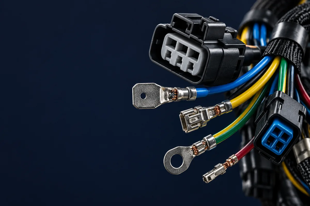
Select a power cable assembly by its system voltage, corrected ampacity, voltage drop, termination ratings and installation environment. Approve the cable, connectors and assembly together: an insulation temperature rating or conductor size alone does not establish the usable current of the finished assembly.
Use the tables below to prepare a specification and check the arithmetic. All ampacity, derating and circuit-sizing decisions remain subject to the latest applicable codes and product ratings and must be confirmed by a qualified electrical engineer. Public reference tables do not replace the complete adopted code.
For the assembly fundamentals, see the cable assembly vs wire harness comparison and custom cable assembly process guide. The power cable assembly service is the related manufacturing route for a drawing-based RFQ.
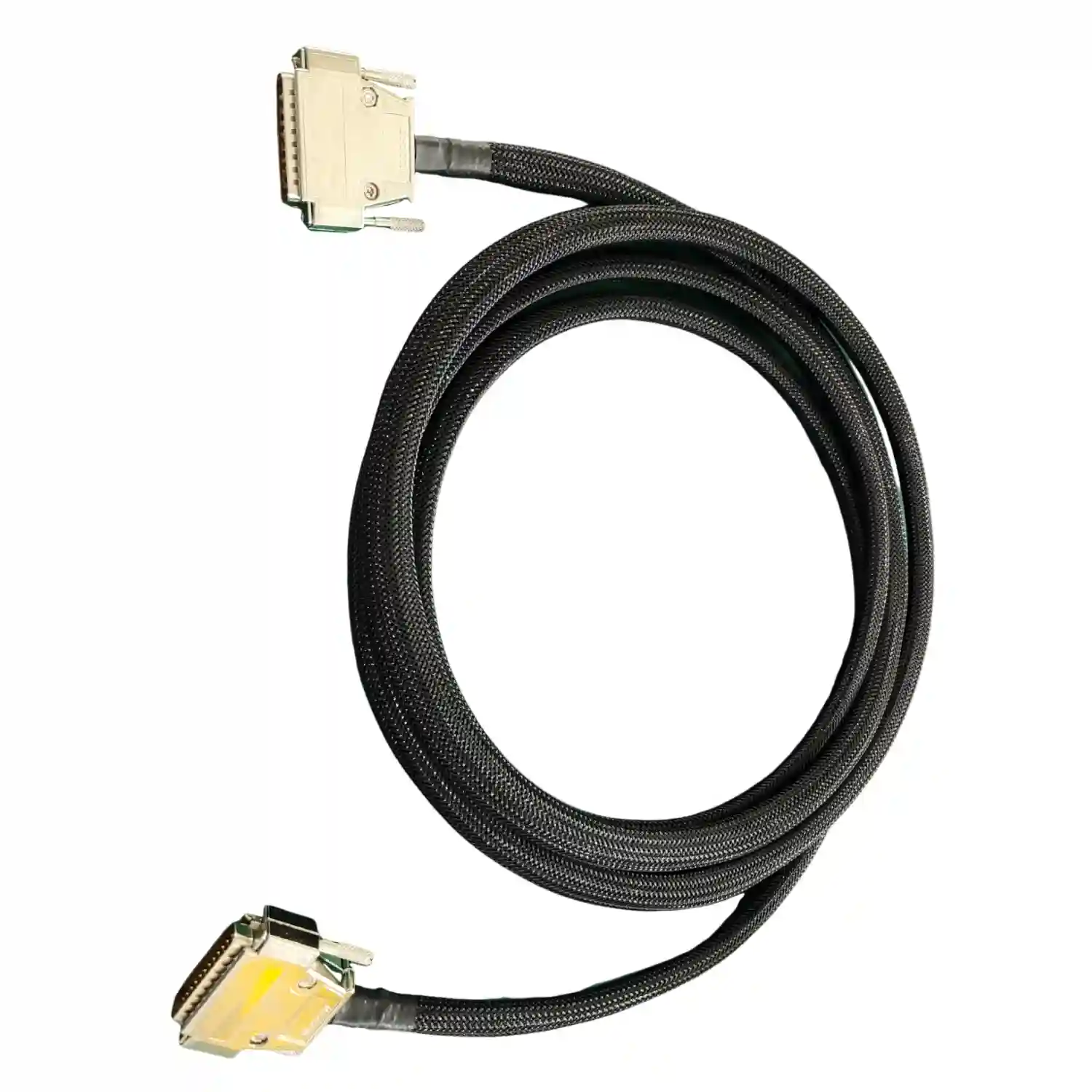
Power Cable Voltage Classifications
Specify the actual AC or DC system voltage and the cable rating before using labels such as low, medium or high voltage. IEC 60038 supplies preferred system-voltage and equipment-design reference values; it is not a universal cable-selection table. The standard scopes below deliberately overlap.
| Reference / class | Verified scope or rating | What to record |
|---|---|---|
| Low-voltage installation reference | IEC 60364-1 covers circuits up to 1,000 V AC or 1,500 V DC. | State nominal and maximum system voltage, AC/DC and grounding arrangement. |
| IEC 60502-1 cable scope | Rated AC voltages of 1 kV and 3 kV. | Name the cable standard and complete voltage designation; do not infer a system class from the title. |
| Medium-voltage cable reference | IEC 60502-2 covers rated voltages from 6 kV to 30 kV. | Confirm insulation system, accessories and installation requirements against the selected standard. |
| Higher-voltage cable-system reference | IEC 60840 covers rated voltages above 30 kV through 150 kV. | Review the complete cable-and-accessory system; the scope is not a universal HV boundary. |
| North American product ratings | 600 V and 2 kV are available cable ratings; UL describes MV cable testing from 5 kV to 35 kV. | Identify the NEC wiring method and exact product listing. These values do not define three NEC voltage classes. |
Sources: IEC 60038; IEC 60364-1 scope; IEC 60502-1; IEC 60502-2 amendment scope; IEC 60840; Southwire 600 V example; Service Wire 2 kV example; UL MV/HV testing scope.
The UL documents have different roles: UL 1581 is a reference standard for electrical wires, cables and flexible cords; UL 44 addresses thermoset-insulated wires and cables; UL 62 addresses flexible cords and cables. A reference to a test standard is not proof that a finished assembly has a particular listing. Ask for the product identity and evidence applicable to the quoted construction.
Sources: UL 1581 title and scope; Southwire: UL 44 reference; UL 62.
For a high-voltage cable assembly inquiry, supply the equipment specification and required approval scope. Do not substitute a service-page label for the engineering definition of the circuit.
Insulation Materials: PVC vs XLPE vs EPR
Compare documented constructions, not generic polymer rankings. The temperature figures here are normal conductor operating ratings for named products. They are not ambient-temperature limits, terminal ratings, or promises that every cable made from that material performs identically.
| Material | Verified temperature example | Construction / characteristics | Checks still required |
|---|---|---|---|
| PVC | Southwire SPEC 44066 THHN/THWN-2: 90°C wet or dry. | PVC insulation with nylon jacket and flexible stranded copper; manufacturer specifies oil, gasoline and sunlight resistance. | Confirm terminal compatibility, routing and required movement qualification. |
| XLPE | Southwire SPEC 10006 XHHW-2/RW90: 90°C wet or dry. | Cross-linked polyethylene insulation; SIMpull construction is designed for installation without pulling lubricant. | Check exact size, voltage marking and installation method; pulling performance does not establish flex life. |
| EPR | Southwire SPEC 45005 RHH/RHW-2: 90°C wet or dry. | Ethylene propylene rubber insulation with a thermoset CPE jacket; product documentation identifies oil and sunlight resistance. | Confirm jacket exposure, bend limits and termination system. |
| Emergency / short-circuit limits | Refer to the selected model datasheet. | Do not transfer an emergency rating between constructions. | Specify permitted duration and the required engineering assessment. |
Sources: Southwire SPEC 44066; Southwire SPEC 10006; Southwire SPEC 45005.
Request separate evidence for flame behavior, smoke, chemicals and mechanical use. Neither a material abbreviation nor a temperature marking establishes all of those properties. UL’s application guide explains why the exact cable markings and intended use matter. Keep insulation and outer-jacket requirements separate on the BOM, especially when an alternate material is proposed.
Sources: UL wire and cable application guide.
Conductor Materials & Wire Gauge Selection
Start with conductor material, size and stranding on the drawing. Do not approve a copper-to-aluminum change, or a change to finer stranding, solely because the quoted current is similar. Ask the supplier to confirm that the specified terminal, tooling and installation instructions cover the proposed conductor construction.
| AWG | Nominal area (mm²) |
|---|---|
| 14 | 2.08 |
| 12 | 3.31 |
| 10 | 5.26 |
| 8 | 8.37 |
| 6 | 13.3 |
| 4 | 21.2 |
| 2 | 33.6 |
| 1/0 | 53.5 |
Sources: Rittal technical guide, printed page 38.
Keep the original size designation in the BOM when comparing suppliers. A rounded metric description can conceal a different conductor construction. Provide the terminal part number and wire specification together, then require written approval for an alternate. Use the AWG and ampacity guide as related reading; the installation conditions below still govern the calculation.
Industrial Power Connector Standards
IEC 60309-1 covers plugs, fixed or portable socket-outlets and appliance inlets primarily for industrial use, indoors or outdoors. NEMA WD 6 addresses wiring-device dimensions and configurations; its scope includes plugs, receptacles and wall plates. Straight-blade and locking devices are configuration categories, not interchangeable connector families.
Sources: IEC 60309-1 scope; NEMA WD 6 scope; Leviton: NEMA straight-blade and locking devices.
Specify the complete mating pair, configuration, poles and grounding contacts, voltage/current approval, cable-entry range and environmental condition. Check whether protection claims apply when mated, unmated or capped. Avoid selecting an industrial connector from color alone, and confirm any required interlock or disconnection procedure with the equipment designer.
IEC 60320 appliance couplers
Appliance couplers are a separate interface family. Interpower lists the international C13/C14 rating as 10 A at 250 V and the C19/C20 rating as 16 A at 250 V. Its guide distinguishes 70°C, 120°C and 155°C pin-temperature categories; these are not cable ambient ratings. Regional approvals and the exact part determine the usable assembly rating.
Sources: Interpower: C13 and C19 ratings; Interpower: IEC 60320 temperature categories.
Record both connector part numbers and the applicable approval in the RFQ. Include contact termination, strain relief and any shield connection on the drawing. If a supplier proposes another connector series, request a mating and rating review before accepting the substitution.
Ampacity Calculations & Derating Factors
Read the base table, apply required correction and adjustment factors, then check terminal and equipment limits. Table 310.16 values below apply to copper conductors with not more than three current-carrying conductors in a raceway, cable or earth (direct burial), at 30°C ambient. They are not a universal ampacity table for flexible cords or every assembled cable.
| AWG | 60°C (A) | 75°C (A) | 90°C (A) |
|---|---|---|---|
| 14 | 15 | 20 | 25 |
| 12 | 20 | 25 | 30 |
| 10 | 30 | 35 | 40 |
| 8 | 40 | 50 | 55 |
| 6 | 55 | 65 | 75 |
| 4 | 70 | 85 | 95 |
| 2 | 95 | 115 | 130 |
| 1/0 | 125 | 150 | 170 |
Sources: Southwire MC installation guide: NEC table reprint; Mike Holt: Table 310.16.
Southwire’s public reprint uses the earlier table number 310.15(B)(16); the selected values also match the Table 310.16 rows in Mike Holt’s reference. Small-conductor overcurrent-protection rules can limit a circuit below a higher-temperature table value. Do not select a breaker directly from this table or treat the 90°C column as a terminal rating.
Ambient-temperature correction
| Ambient (°C) | 60°C insulation | 75°C insulation | 90°C insulation |
|---|---|---|---|
| 31–35 | 0.91 | 0.94 | 0.96 |
| 41–45 | 0.71 | 0.82 | 0.87 |
| 56–60 | — | 0.58 | 0.71 |
Sources: PACE continuing education: Table 310.15(B)(1).
A dash is not a zero-current factor to insert into a formula; that table does not supply a usable factor for the stated combination. Use the conductor temperature column appropriate to the actual insulation and wet/dry condition. Check table numbering in the adopted edition.
Adjustment for current-carrying conductors
| Current-carrying conductors | Adjustment factor |
|---|---|
| 4–6 | 80% (0.80) |
| 7–9 | 70% (0.70) |
| 10–20 | 50% (0.50) |
| 21–30 | 45% (0.45) |
| 31–40 | 40% (0.40) |
| 41 or more | 35% (0.35) |
Sources: Mike Holt: Table 310.15(C)(1), printed page 374.
Count current-carrying conductors under the code’s neutral and grounding-conductor rules, not simply every wire visible in the cable. Confirm the actual raceway or bundling arrangement and any exception before choosing a factor.
Worked example: 4 AWG copper in a hot, shared raceway
Assume 90°C insulation suitable for the location, 60°C ambient, six current-carrying conductors, applicable correction/adjustment rules with no exception, 75°C-rated terminals, and equipment suitable for the stated ambient. These are teaching inputs, not a specified customer installation.
Base ampacity: 95 A from the 4 AWG, 90°C column. Temperature correction: 0.71 from the 56–60°C ambient row. Conductor-count adjustment: 0.80 for six conductors. First, 95 × 0.71 = 67.45 A; then 67.45 × 0.80 = 53.96 A. The 4 AWG, 75°C terminal-column value is 85 A, so it does not further limit this calculated result.
Sources: Southwire: 4 AWG table values; PACE: temperature factor; Mike Holt: conductor-count factor and termination check.
53.96 A is a corrected conductor ampacity, not a breaker selection or an approved continuous load. Complete the load calculation, protection coordination and equipment checks separately. All ampacity and derating decisions are subject to the latest applicable codes and product ratings and must be confirmed by a qualified electrical engineer. The quality testing guide can help define assembly records; testing does not replace circuit sizing.
Voltage Drop: Formula, Resistance Data & Example
For a resistive two-wire DC circuit, or a simplified single-phase estimate that neglects reactance and assumes unity power factor, use V_drop = 2 × I × R × L / 1000. I is current in amperes, R is conductor resistance in Ω/1000 ft at the assumed conductor temperature, and L is one-way length in feet. The factor of two includes the outgoing and return conductors.
| AWG | Resistance (Ω/1000 ft) |
|---|---|
| 10 | 1.240 |
| 8 | 0.778 |
| 6 | 0.491 |
Sources: Mike Holt: voltage-drop calculations, printed page 219.
Worked example: a resistive single-phase circuit
Assume a 240 V supply, 40 A load, 100 ft one-way run and 6 AWG uncoated stranded copper. For this calculation only, use the table’s 75°C conductor resistance of 0.491 Ω/1000 ft. Assume negligible contact resistance and reactance. These inputs illustrate the method; they do not establish ampacity compliance or predict the actual operating temperature.
Loop resistance = 2 × 100 × 0.491 / 1000 = 0.0982 Ω. Voltage drop = 40 × 0.0982 = 3.928 V. Percentage drop = 3.928 / 240 × 100 = 1.637%, leaving 236.072 V at the load under these assumptions. An assumed 3% design budget is 7.2 V, so this simplified estimate falls below that budget.
The commonly cited 3% branch-circuit and 5% combined feeder-plus-branch figures are general design recommendations in NEC informational notes, not universal mandatory limits. Schneider Electric explicitly distinguishes this guidance from a requirement. Check special applications, local requirements, equipment tolerances and the upstream drop before setting the project budget.
Sources: Schneider Electric: system voltage considerations.
For AC loads with appreciable reactance, non-unity power factor or motor starting, obtain an appropriate impedance-based calculation. Do not reuse the two-wire factor for a three-phase system. A voltage drop calculator is only a cross-check when its units, circuit model and temperature assumptions match the design.
Industrial Applications: Parameters to Check
Use this worksheet to collect requirements from the equipment owner. These are review prompts, not claims that a material or voltage class is automatically suitable for an industry. Attach the relevant equipment manuals and environmental requirements to the RFQ.
| Application | Electrical parameters | Environment / mechanical checks |
|---|---|---|
| Motors and variable-frequency drives | Supply and motor voltage, running/starting current, drive-manufacturer cable and shielding instructions. | Oil exposure, routing, shield termination, grounding and fixed versus moving sections. |
| Distribution and control cabinets | Feeder/load current, terminal temperature ratings, conductor count and fault-protection requirements. | Enclosure hot spots, wiring space, bend radius, cable entry and strain relief. |
| Energy storage and batteries | Maximum DC voltage, charge/discharge current profiles, polarity and protection coordination. | Terminal geometry, installation access, fluids, vibration, insulation protection and service disconnection. |
| Welding equipment | Equipment current/duty information, cable length and manufacturer-specified cable construction. | Handling, abrasion, heat exposure, connector compatibility and routing. |
| Cranes and moving machinery | Load profile, supply voltage, grounding and connector retention. | Bending, torsion, travel, hanging loads, oil, weather and required movement qualification. |
| Renewable energy installations | Maximum system voltage, current profile and required wiring method. | Sunlight/UV, moisture, site temperature, routing and burial requirements where applicable. |
| Data-center equipment | Actual inlet/receptacle approvals, load distribution and supply arrangement. | Cord retention, rack routing, airflow-space requirements and identification. |
Related manufacturing scopes include battery cable assemblies and industrial panel wiring. For motion requirements, consult the robotics and industrial automation pages. Describe the operating conditions even when an industry name appears on the purchase order.
Power Cable Selection Checklist
Send a controlled information package rather than a gauge-and-length request. The table below is a proposed RFQ worksheet: agree unresolved items before releasing manufacture, and identify who owns electrical design approval.
| Parameter | Why it affects selection | Information to give the supplier |
|---|---|---|
| System voltage | Sets the required cable and interface rating review. | Nominal/maximum voltage, AC/DC, grounding arrangement and equipment specification. |
| Load and protection | Ampacity and protective-device decisions need the circuit context. | Running, continuous, peak and starting loads; duty profile; protection design. |
| Thermal / installation conditions | The base table may require correction and adjustment. | Ambient/hot spots, wiring method, conductor count and terminal temperature ratings. |
| Length and voltage drop | A thermally acceptable conductor may miss the voltage budget. | One-way route length, circuit model, allowed drop and upstream allowance. |
| Conductor / insulation | Material and stranding must match the termination system. | Cable manufacturer/part number, AWG, strands, insulation, jacket and color. |
| Connections | Mating and retention depend on the complete interface. | Connector, contact, lug and seal part numbers; pinout; shield/ground details. |
| Exposure / motion | Environmental and mechanical requirements need separate evidence. | Fluids, oil, UV, moisture, temperature, bend/torsion conditions and strain relief. |
| Acceptance / change control | The quote must include the intended verification scope. | Drawing revision, tests and limits, sampling, traceability and approved alternates. |
Use the wire harness RFQ checklist to add quantity tiers, delivery, packaging and documentation requirements. Include a drawing PDF, controlled BOM and connection table. Mark open requirements explicitly; require the quotation to identify assumptions and exclusions before accepting samples or production parts.
Frequently Asked Questions
What's the difference between SOOW and SJOOW cable?
Southwire’s line card identifies SOOW products rated 600 V and SJOOW products rated 300 V. Match the exact cord specification, installation permission and connector approvals; the type name alone does not establish the complete assembly rating.
Can I use extension cords for permanent installations?
Do not substitute an extension cord for fixed structural wiring. OSHA 1910.305(g)(1)(iv) prohibits this unless a specified permitted use applies. Have a qualified electrical engineer confirm the applicable code, wiring method and product ratings for the installation.
Why do some power cables have shielding?
Shielding is part of an electromagnetic-compatibility design. For a drive or noise-sensitive installation, obtain the equipment manufacturer’s specified cable construction and shield-termination instructions. Do not impose a universal grounding arrangement on every power cable assembly.
Sources: Belden: VFD cable noise-control and termination resources.
What does “plenum rated” mean for power cables?
Do not infer permission for power wiring in an air-handling space from a communications-cable marking or an LSZH description. Ask for the exact cable category, permitted wiring method and applicable approval. UL’s application guide distinguishes intended uses and markings.
How do I calculate voltage drop for long cable runs?
Use the circuit model, one-way length, current and resistance at the assumed conductor temperature. The worked two-wire example above shows each step. Recheck AC impedance, equipment tolerances and upstream drop before accepting the result.
Does 90°C insulation allow the 90°C ampacity at every terminal?
No. Correction and adjustment may start from the appropriate insulation column, but the result must respect the termination and equipment limits. The latest applicable codes and product ratings govern; a qualified electrical engineer must confirm the design.
Can I use Table 310.16 for a flexible power cord?
Do not assume that table applies. Select the table and installation rules for the actual cable or cord type, then check the complete assembly. Have a qualified electrical engineer confirm the latest applicable code requirements and product ratings.
Sources: Southwire cord line card; OSHA flexible-cord rules; UL markings and applications; Mike Holt: temperature and termination limits.