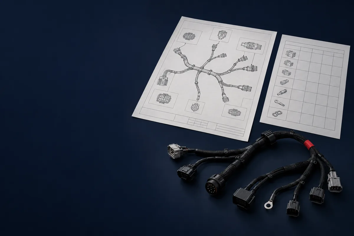
A wire harness prototype is ready to build when the drawing, bill of materials, connector pinouts, wire list and test criteria are all written down and agree with each other. Most prototype delays are not build problems; they are clarification loops on a missing mating-connector part number, an unstated tolerance or an undefined test limit. This guide lists what to prepare, the six stages a prototype passes through, eight design-for-manufacturing (DFM) mistakes worth catching before tooling, when to build in-house versus outsource, and what a first article inspection (FAI) file should contain.
Build time depends on connector lead times, circuit count and test scope, so this guide gives no fixed schedule. Ask the supplier to confirm the material and sample dates in writing for your bill of materials. Acceptance criteria, test limits and sampling plans come from your drawing and the standards you cite; the sections below tell you what to specify, not what number to use.
Three Types of Wire Harness Prototype
The word “prototype” covers builds with different goals. Say which one you are ordering, because the materials, tooling and documents differ.
| Type | What it proves | Typical build method | Gate before next stage |
|---|---|---|---|
| Proof of concept | The circuit and connector choices work electrically. | Hand-built, often with stock or substitute components. | Electrical function confirmed on the bench. |
| Functional prototype | The harness fits the enclosure or vehicle and survives your validation tests. | Production-intent wire, terminals and connectors; hand assembly with reusable fixtures. | Fit check, continuity and the environmental or mechanical tests you defined. |
| Pre-production / first article | The process can build the harness repeatably to the drawing. | Production methods, fixtures and test equipment. | First article inspection signed off against the drawing. |
Skipping the functional stage moves design problems into production, where they surface as scrapped material, rework and a delayed launch. How many units to build at each stage is a validation-plan decision: count the units consumed by destructive tests, the units needed for fit checks, and one retained reference sample.
The Prototype Readiness Checklist: 12 Items to Prepare
Send the full package with the first request for quote so the supplier can quote and review once, not in pieces. The same documents feed the RFQ checklist and the engineering drawing and DFM review.
| Item | What it contains | Note |
|---|---|---|
| 1. Wiring diagram or schematic | Defines every net and splice. | Revision letter on the document. |
| 2. Dimensioned harness drawing | Branch lengths, break-out points and overall length. | State the length tolerance; do not leave it to the supplier. |
| 3. Bill of materials | Manufacturer and part number for every connector, terminal, seal, wire and sleeve. | Name an approved alternate for any single-source part. |
| 4. Connector and cavity pinout | Which wire goes to which cavity, viewed from which side. | State the view (mating face or wire entry) on the drawing. |
| 5. Wire list | Gauge, insulation type, color or stripe, and length per circuit. | Mark colors that carry information so they are not substituted. |
| 6. Terminal-to-wire matches | Which terminal crimps onto which wire size. | Use the terminal manufacturer's application specification. |
| 7. Mating-part information | Part numbers of the connectors this harness plugs into. | A missing mate is the most common cause of a clarification loop. |
| 8. Protection and routing notes | Sleeving, tape, clips, grommets and where they sit. | Mark where abrasion or heat is expected. |
| 9. Labeling and marking | Wire, connector and harness identification. | Specify content and position; see the labeling guide. |
| 10. Test requirements | Continuity netlist, insulation tests and mechanical tests. | Give limits, not just “100% tested”. |
| 11. Acceptance standard and class | The workmanship standard and class the build is judged against. | Cite the revision, for example IPC/WHMA-A-620 Revision F, and the class. |
| 12. Quantity, delivery and revision plan | How many units, by when, and whether a second revision is expected. | Say which units are destructive-test samples. |
The Six Stages of a Prototype Build
Each stage has an input, an output and a gate. A gate that is not written down is where a build stalls.
| Stage | What happens | Output | Gate |
|---|---|---|---|
| 1. Document review | Supplier checks the drawing, BOM, pinouts and wire list against each other and lists open questions. | Written question list and your answers. | All questions closed and the revision frozen for this build. |
| 2. Material procurement | Connectors, terminals, seals and wire are ordered; long-lead items set the schedule. | Confirmed material delivery dates. | Parts received and checked against the BOM. |
| 3. Process setup | Cut, strip and crimp settings are set for each terminal and wire; a crimp pull test and crimp-height or cross-section check validates the setup. | Setup crimp records. | Crimps meet the terminal manufacturer's specification. |
| 4. Assembly | Wires are cut, terminated, inserted into connectors and laid on a board; protection and labels are applied. | Build record with lot numbers. | Visual inspection against the cited acceptance standard. |
| 5. Test | Continuity and any insulation or mechanical tests run against the netlist and limits you supplied. | Test records tied to the unit serial. | All specified tests pass; failures are logged and analysed. |
| 6. Review and ship | You fit-check the sample; the supplier packs and ships with the inspection records. | Inspection report and photos. | Your sign-off, or a list of changes for the next revision. |
Stage 2 usually sets the schedule: specialty or sealed connectors can be the last item to arrive, and nothing ships until they do. Stage 3 matters more than it looks, because a crimp that reads fine on continuity can still be under-crimped; the pull-force minimum comes from the terminal manufacturer's application specification and the standard you build to. See the crimping guide.
DFM: 8 Mistakes to Catch Before Production
Design for manufacturability review during prototyping is cheaper than a change after tooling. These eight mistakes are common documentation and design gaps; each has a specific fix you can put on the drawing.
| Mistake | Effect | Prevention |
|---|---|---|
| Mating connector not specified | The supplier builds to the wrong keying, gender or seal. | Put the mating part number on the drawing. |
| Wire gauge and terminal do not match | Under-crimped or oversized crimps that can pass continuity and fail in service. | Take the wire-range for each terminal from the manufacturer's application specification. |
| No tolerance on branch lengths | Harness does not fit the enclosure even though every length is “as drawn”. | State a tolerance per branch and confirm against the mating hardware. |
| No strain relief or bend-radius control at the connector | Conductor fatigue at the crimp or connector exit under vibration or handling. | Specify boots, clamps or clip positions and the minimum bend radius from the wire and connector datasheets. See the strain relief guide. |
| Pinout view not stated | Wires terminated mirror-image to the intended cavities. | Mark whether the pin view is the mating face or the wire entry. |
| Wire colors left ambiguous | Wrong substitute color or stripe is used; field service cannot trace circuits. | List the color of every circuit and mark which colors may not change. |
| Sealed connector without wire-seal match | Moisture ingress because the wire outer diameter is outside the seal range. | Check the insulation diameter against the seal range in the connector datasheet. |
| Test criteria undefined | “Tested” means different things to you and the supplier; escapes reach the field. | Provide a netlist and the limits for continuity, insulation and pull tests. |
See also the wire harness design guide. A review done at the prototype stage is the point of the DFM review service.
DIY vs Outsource: A Decision Framework
The answer depends on complexity, capability and what the prototype has to prove. Score each row for your project; if most land on the right, build with a supplier. The broader in-house vs outsourcing guide and the manufacturer selection guide cover the production decision.
| Factor | In-house is reasonable when | Outsource when |
|---|---|---|
| Circuits and connector complexity | Few circuits, common connectors, hand tools adequate. | Many circuits, branches, sealed or specialty connectors. |
| Crimp capability | You have the application tooling for each terminal and can verify crimps. | Terminals need dedicated applicators or crimp-quality verification you do not have. |
| Test capability | Multimeter and megohmmeter cover the test plan. | Continuity netlist testing, high-potential or documented records are required. |
| Standards and records | No formal acceptance class or traceability required. | A workmanship class, FAI records or customer approval is required. |
| Volume path | One-off bench build. | Prototype is the start of a production program; the same supplier can carry it forward. |
| Schedule risk | Parts are in stock and your time is free. | Engineering time is the constraint, or long-lead parts need sourcing. |
Testing Your Prototype: Manual vs Automated
Choose the test method from circuit count and what the prototype must prove. A multimeter and megohmmeter are enough for a few circuits and a one-off build; a netlist-driven tester is better for many circuits or when the same test will carry into production. The crossover depends on build quantity, circuit count and the coverage you need, so compare manual test labor with fixture, programming and maintenance cost for your case.
| Aspect | Manual | Automated |
|---|---|---|
| Equipment | Multimeter, megohmmeter | Netlist tester and fixture sized to the circuit count |
| Coverage | Depends on the procedure and the operator | Depends on the programmed netlist and validated limits |
| Records | Written by hand | Logged against serial number |
| Best for | Simple circuits and one-off prototypes | Complex circuits and pre-production articles |
For the three families of electrical and mechanical tests and what each catches, see the quality testing methods guide.
First Article Inspection: What the File Contains
FAI verifies that the first unit built with production-intent methods meets every requirement on the drawing. Agree the file contents with the supplier at quote time; the table lists the usual items. For the full process see the first article inspection guide. Automotive programs often require a PPAP submission as well; see the PPAP guide and confirm with your customer which elements apply.
| Document | Purpose |
|---|---|
| Ballooned drawing | Every dimension and note numbered, matched to a measurement. |
| Bill of materials with lot or date codes | Proves the parts are the ones on the BOM. |
| Material and supplier documentation | Datasheets and, where required, certificates of conformance for wire and connectors. |
| Dimensional report | Measured lengths and positions against the drawing tolerances. |
| Crimp records | Pull-force results and crimp-height or cross-section checks for each terminal and wire pair. |
| Electrical test results | Continuity, plus insulation tests if specified, tied to the unit serial. |
| Visual inspection record | Inspection against the cited acceptance standard and class. |
| Photographs | Overall, each connector, labels and any protection. |
| Sign-off | Who inspected, who approved, and the date. |
Five typical FAI nonconformances to check first
These are typical categories, not a ranking by frequency. Checking them before the first article is submitted prevents most repeat submissions.
| Nonconformance | What it looks like | Prevention |
|---|---|---|
| Dimension out of tolerance | Branch length or break-out position differs from the drawing. | Agree the tolerance before the build and measure at the stated reference points. |
| Wrong or unrecorded material | A substitute connector, seal or wire, or no lot trace. | Freeze the BOM; log lot or date codes at the station. |
| Crimp not verified | Setup records or pull results missing for one terminal-wire pair. | List every pair in the plan and test at setup and after changes. |
| Label or marking nonconformance | Wrong content, position or legibility. | Approve a label sample before the build. |
| Test record incomplete | Results not tied to a serial, or limits not stated. | Define the test list and record format in the plan. |
From Prototype to Production
A signed-off prototype is not yet a production process. Before release, confirm what changes: production fixtures and applicators replace hand setups, test moves to a validated fixture, labels and packaging are fixed, and the revision is frozen under change control (see the revision control guide). Allow for a second prototype revision before freezing, and budget it by the changes involved and the fixtures that can be reused. The custom cable assembly process guide covers the production flow.
Frequently Asked Questions
How long does a wire harness prototype take?
It depends on design complexity, material availability, test scope and the supplier's confirmed schedule. Specialty connectors with long lead times usually set the date, because the prototype cannot ship until they arrive. Ask for the material and sample dates in writing for your BOM.
How many prototype units should I order?
Choose from the validation plan: fit checks, electrical tests, environmental or mechanical validation, units consumed in destructive tests and one retained reference sample. A single unit leaves no margin if it is consumed in testing.
What documentation do I need to start a prototype?
At minimum a wiring diagram or schematic, a dimensioned drawing, a bill of materials, a connector pinout and a wire list with gauges and lengths. Add mating-part numbers, test limits and the acceptance class to avoid clarification cycles.
Do prototypes use production tooling?
Generally no. Prototypes are built by hand assembly with reusable fixtures, and dedicated production tooling is introduced after the design is validated and the volume justifies it.
How much does a wire harness prototype cost?
Prototype pricing reflects manual labor and small-quantity material purchases, so the per-unit cost is high relative to production. The amount depends on build and test scope, so request a quote against your documents.
What is the difference between a prototype and a pre-production run?
A prototype validates the design: does it fit, function and meet specification. A pre-production run validates the process: can it be built repeatably with production methods, fixtures and test. Pre-production ends with the first article inspection.
Next Step
Send the drawing, BOM, pinouts and test requirements through the contact page, and mark the acceptance class and revision. See the capabilities page for the build and test processes.
Sources: IPC, IPC/WHMA-A-620 standards page; Circuits Assembly, IPC/WHMA-A-620 explained. Terminal pull-force and crimp requirements come from the terminal manufacturer's application specification for the part you select.