Technical Guide
How to Depin a Connector:
Safe Terminal Removal Steps, Tools, and Rework Rules for Wire Harness Teams
A connector repair that should take 5 minutes can scrap a full harness when the wrong release tool bends the retention lance, damages the cavity seal, or mixes terminal positions during reassembly. This guide explains how to depin a connector safely, which tools and checks matter most, when a terminal can be re-used, and what buyers should define before approving depinning as a repair method.
is a normal depinning window for a documented repair on a simple single-lock connector when the correct release tool is already available
is enough to turn an acceptable rework into a scrap connector because terminal retention can fall below specification immediately
terminal position verification is the minimum expectation after depinning and reinsertion on production harnesses
are common on sealed automotive connectors: a primary terminal lance plus a secondary lock or TPA that must be handled in the right order
- 1. Why Depinning Becomes a Quality Problem Fast
- 2. Tools and Connector Anatomy You Must Understand First
- 3. Step-by-Step Depinning Workflow
- 4. Failure Modes and Terminal Reuse Rules
- 5. RFQ and Work Instruction Inputs Buyers Should Define
- 6. Frequently Asked Questions
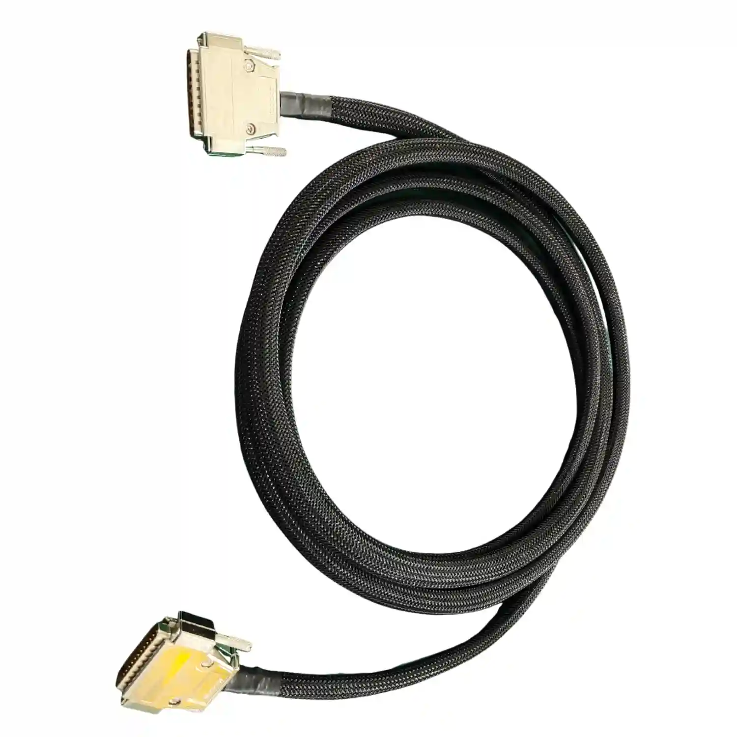
Industrial cable assembly with connector terminations undergoing inspection before terminal removal, reinsertion, and electrical retest
Depinning is not just a connector repair task. It affects retention force, seal integrity, pin mapping, takt time, and final test coverage across the whole harness.
Depinning a connector sounds simple until it happens on a live production harness. A technician pushes in the wrong release blade, the terminal lance is flattened, the cavity seal twists, and a repair that was supposed to save one assembly now creates a hidden retention failure. That is why good harness teams treat depinning as a controlled rework process, not a casual bench fix.
Most connector problems do not come from the removal step alone. They come from incomplete connector identification, skipping the secondary lock, pulling on insulation instead of the conductor support, or reusing a terminal after the locking feature has already been deformed. When those mistakes happen on sealed automotive, medical, or industrial harnesses, the result is usually intermittent contact, reduced pull-out strength, or water ingress that appears only after vibration and service cycles.
This guide is written for OEM buyers, quality engineers, repair teams, and manufacturing managers working with wire harnesses and custom cable assemblies. It focuses on production-grade depinning: how to remove terminals without damaging the connector, which tools belong in the work instruction, when the terminal must be replaced instead of reused, and what checks should be completed before the harness goes back to stock or to the customer.
1. Why Depinning Becomes a Quality Problem Fast
In production, depinning is usually triggered by one of four events: a terminal inserted into the wrong cavity, a damaged wire or seal discovered at inspection, a component revision change, or a field-return repair. The risk is that teams focus on getting the terminal out, not on preserving everything around it. A connector can look visually acceptable after rework and still fail retention, continuity, or ingress tests later.
The first cost driver is hidden damage. Many modern connectors use a primary retention lance and a secondary lock or terminal position assurance feature. If the release tool enters from the wrong face or at the wrong angle, it can permanently deform the retention geometry. That turns a recoverable pin-map error into a new defect. This is the same reason our wire harness connector selection guide and wire harness crimping guide put so much emphasis on connector family, terminal style, and verified tooling.
The second cost driver is traceability. If the harness uses sealed cavities, color-coded wires, and mixed gauge circuits, one depinning action can create a repinning mistake that is harder to catch than the original error. Buyers who need dependable rework control should align depinning with the same inspection logic used in our IPC/WHMA-A-620 inspection guide, our wire harness quality testing guide, and the process discipline behind an electrical connector system with defined retention features.
Depinning also changes the economics of repair. If the connector is low-cost and globally stocked, replacing the housing and terminal may be faster than a careful rework. If the connector is customer-owned, keyed, or has a long lead time, then controlled depinning can protect delivery dates. The decision should be based on total installed risk, not just the part price.
Flattening the primary lance or over-opening the terminal spring can create a defect that passes visual review but fails after vibration or pull load.
On sealed connectors, a twisted grommet or nicked cavity seal can destroy the intended IP67 or IP68 performance without obvious external evidence.
Once multiple wires are released from a high-cavity connector, wrong reinsertion becomes a larger risk than the original repair unless cavity control is documented.
A 3-minute shortcut in rework can cost hours later if the harness has to be re-opened, electrically retested, or fully rebuilt.
Quote
Text: If a connector has 24 cavities and two locking stages, depinning without a written sequence is not a repair method. It is a scrap decision disguised as rework. One bent lance can consume 30 to 45 minutes of diagnosis after final test.
Author: Hommer Zhao
Role: Technical Director
2. Tools and Connector Anatomy You Must Understand First
Before anyone removes a terminal, they need to identify the connector family, the terminal type, and the locking logic. Open-barrel crimp contacts, stamped blade terminals, box contacts, coaxial pins, and high-current lug-style contacts all release differently. The release tool that works on one family can permanently damage another. That is why experienced teams verify the connector drawing or OEM service document before touching the harness.
Most depinning failures happen because the operator does not distinguish between the primary lock and the secondary lock. Many automotive and industrial connectors use a TPA, wedge lock, rear retainer, or front insert that must be moved to a service position first. If that step is skipped, the release tool is fighting the wrong feature. Related concepts from crimp termination and IP protection matter here because terminal geometry and sealing parts determine how much damage the repair can tolerate before the assembly stops meeting specification.
Tooling should also be matched to access direction. Some terminals release from the mating face with a tube or blade, others from the wire side, and some require a dedicated extraction sleeve plus support fixture. Generic picks can work for teardown, but they are a poor standard for production rework because they introduce too much variation in angle, force, and surface damage.
Table
| Connector / Terminal Situation | Typical Release Method | Best Tool Type | Main Risk If Wrong Tool Is Used | Reuse Outlook |
|---|---|---|---|---|
| Sealed automotive open-barrel terminal with TPA | Service secondary lock first, then depress lance from front or rear per design | OEM depinning blade or tubular extractor | Bent lance or torn cavity seal | Housing sometimes reusable; terminal often replaced if lance is touched |
| Unsealed board-to-wire crimp contact | Depress locking tang through housing window | Fine flat release pick sized to contact family | Window damage or tang over-bend | Possible reuse only after retention check |
| Circular connector contact with retention clip | Dedicated insertion/extraction tool through rear grommet or insert | Matched extraction sleeve | Insert damage or contact plating scratches | Usually replace contact on controlled assemblies |
| Coaxial pin or socket contact | Release via connector-specific sleeve and support body | Precision coax extraction tool | Center contact distortion and impedance instability | Low reuse tolerance on RF assemblies |
| High-current power contact | Unlock wedge or retainer, then withdraw with axial support | Heavy-duty extractor and cavity support | Housing crack or contact spring loss | Replace contact when heat marks or spring damage are present |
Note: If the tool description in the work instruction says only "small pick," the process is not controlled enough for production rework.
Quote
Text: Around 80% of depinning damage we audit traces back to one issue: the technician knew the connector series but did not know the exact terminal family or secondary lock position. Identification comes before extraction every time.
Author: Hommer Zhao
Role: Technical Director
3. Step-by-Step Depinning Workflow
The safest depinning workflow starts before the harness is touched. Confirm the cavity number, wire color, wire gauge, terminal part number if available, and whether the connector is sealed or unsealed. If more than one cavity will be reworked, photograph the face view and label the released circuits. This is especially important for mixed-signal harnesses, waterproof connectors, and branch-heavy assemblies built through our prototype cable assembly workflow or waterproof cable assembly service, where repair history often determines whether the sample can still be approved.
Next, move the secondary lock to the service position without forcing it past its designed travel. Support the connector body so the operator is not pushing load into the wire. Insert the correct extraction tool at the specified entry point, depress the retention feature just enough to clear the shoulder, and pull the wire from the rear in line with the terminal axis. Axial pull is critical. Twisting the wire while the lance is partially released can scar the cavity wall or loosen the conductor crimp barrel.
Once the terminal is out, stop and inspect before reinserting anything. Check the lance shape, contact spring geometry, insulation support, conductor brush, cavity seal condition, and plating damage. If the terminal shows deformation, overheating, or scoring, replace it. If the connector cavity is damaged or the secondary lock no longer moves cleanly, replace the housing. After reinsertion, verify full seating, lock position, cavity location, and perform at least continuity and retention confirmation before final test release.
- 1. Confirm connector family, cavity number, and terminal type.
- 2. Move the secondary lock to service position if present.
- 3. Insert the matched extraction tool from the correct side.
- 4. Depress the retention feature without over-travel.
- 5. Pull the wire straight back, not sideways or by insulation only.
- 6. Inspect the terminal, seal, and cavity before reinsertion.
- Terminal fully seated to the same depth as adjacent circuits.
- Secondary lock returned to final position.
- No seal roll, no exposed strands, and no insulation damage near the rear grommet.
- Correct cavity mapping confirmed against drawing or face view.
Checklist
Minimum Rework Bench Controls
- Connector identification reference or service drawing at the station
- Approved extraction tool list by connector family
- Face-view or pin-map marking method before any wire is removed
- Magnified visual inspection after terminal removal
- Continuity and retention verification after reinsertion
When to Escalate Instead of Reworking
- Terminal part number cannot be confirmed
- Housing shows cracks, broken lock tabs, or seal damage
- More than one retention feature has been bent already
- Connector belongs to a regulated medical, aerospace, or high-voltage program with no approved repair instruction
4. Failure Modes and Terminal Reuse Rules
The practical question after depinning is whether the same terminal can go back into service. The answer depends on the terminal family, the severity of handling, and the reliability level of the program. In low-risk bench diagnostics, reuse may be acceptable after retention and visual checks. In automotive, medical, defense, and other controlled harnesses, replacement is usually the safer path because the cost of one intermittent failure is far higher than the cost of one contact.
Three failure modes show up most often. First is locking-lance deformation, where the contact no longer snaps into the cavity with the intended force. Second is contact-zone damage, where the mating spring or pin interface is scratched or spread. Third is seal-system damage, where the terminal may be electrically fine but the connector loses environmental protection. If the harness will be exposed to washdown, coolant, road spray, or outdoor duty, damaged seals should be treated as immediate replacement triggers, not cosmetic defects.
Buyers should also separate rework from salvage. If the connector is on a high-mix harness and only one cavity is wrong, controlled depinning can make sense. If the harness has already seen repeated repair attempts, or if the operator cannot prove retention after reinsertion, the more defensible choice is to replace the terminal and often the housing. That is especially true for programs in automotive, medical, and industrial automation environments where intermittent connector behavior drives expensive diagnosis.
Table
| Observed Condition | What It Means | Can the Terminal Be Reused? | Recommended Action | Why the Call Matters |
|---|---|---|---|---|
| Lance visibly flattened or over-bent | Primary retention is no longer reliable | No | Replace terminal and confirm cavity not damaged | Retention loss can create back-out after vibration |
| Minor cosmetic mark outside mating zone | Handling contact may still be acceptable | Maybe, only after retention check | Inspect under magnification and verify lock engagement | Some marks are harmless, some hide tool slips |
| Seal cut, rolled, or stretched | Environmental barrier is compromised | No | Replace seal and usually replace terminal if seal is captive | Ingress failures appear late and are costly to diagnose |
| Contact spring spread or pin box distorted | Electrical mating force has changed | No | Replace terminal | Contact resistance can drift under load |
| Plating scratched in mating area | Corrosion resistance may be reduced | Usually no on critical programs | Replace terminal, especially in humid or vibrating service | Surface damage accelerates fretting and oxidation |
| Housing lock tab or cavity wall cracked | Connector structure is compromised | Terminal alone is not the issue | Replace housing and inspect adjacent cavities | A cracked body can release multiple circuits |
Note: When a terminal costs cents and a field failure costs hours, replacement is usually the rational choice once any locking or mating geometry has been altered.
Quote
Text: Our default rule is simple: if the depinning step touched the locking lance, the reuse decision is already biased toward replacement. Saving a terminal that costs less than 1% of the harness value is rarely worth the risk on Class 2 or Class 3 style workmanship expectations.
Author: Hommer Zhao
Role: Technical Director
5. RFQ and Work Instruction Inputs Buyers Should Define
If depinning is likely in your service or production flow, define it before the first harness build instead of improvising later. The highest-value inputs are the connector family, approved terminal part numbers, approved extraction tools, reuse rules, and the required verification after rework. Without those details, one supplier will replace the whole connector, another will reuse the terminal, and a third will attempt a bench repair that never should have been approved.
Work instructions should be connector-specific wherever possible. A generic note such as "depin and reinsert as needed" is not enough for sealed connectors, high-cavity housings, or regulated products. Buyers should require face-view references, service-position instructions for secondary locks, terminal replacement triggers, and post-repair test coverage. This aligns with the same sourcing discipline used in our wire harness RFQ checklist and custom cable assembly process guide.
For incoming and outgoing quality, ask for evidence that the repair was controlled. That may include cavity photos, lot-controlled replacement terminals, continuity records, retention checks, and sign-off by a trained operator. If the connector supports waterproof or safety-critical circuits, require the reworked harness to go through the same final test scope as a new harness, not a reduced bench check.
Checklist
What To Put In The RFQ
- Exact connector and terminal family, or clear photos plus mating-part reference
- Whether depinning is allowed in production, prototype only, or prohibited entirely
- Terminal reuse rule: always replace, condition-based, or customer approval required
- Required post-rework tests: continuity, retention, seal inspection, hipot, or full functional test
- Whether replacement terminals and seals must match OEM-approved brands only
What To Put In The Work Instruction
- Secondary-lock release sequence and service position
- Approved extraction tool by connector family
- Photos or diagrams of correct tool entry direction
- Visual reject criteria for lance, seal, housing, and contact zone damage
- Sign-off requirement after reinsertion and retest
6. Frequently Asked Questions
Frequently Asked Questions
Can you depin a connector without the special tool?
Sometimes on simple unsealed connectors, but it is not a good production standard. If the connector uses a secondary lock or a narrow release window, the wrong improvised tool can bend the lance in under 1 second. For controlled harness work, use the connector-specific release tool and verify retention after reinsertion.
Is it safe to reuse a terminal after depinning?
Only when the terminal geometry, locking feature, and mating zone remain intact after inspection. On higher-reliability programs aligned with IPC/WHMA-A-620 style expectations, many teams replace the terminal by default because even a small lance deformation can reduce retention margin materially.
How do you depin a sealed automotive connector?
The normal sequence is to identify the cavity, move the TPA or wedge lock to service position, insert the matched release tool, and withdraw the wire axially while protecting the seal. If the cavity seal is cut or rolled, replace it. For IP67 or higher targets, do not accept seal damage as cosmetic.
What should be tested after repinning a connector?
At minimum, verify 100% cavity position, continuity, and positive terminal retention. Depending on the program, teams may also require contact resistance review, full harness electrical test, hipot, or seal inspection. On safety-critical or regulated assemblies, post-rework testing should match the normal release plan, not a reduced bench check.
When is connector replacement better than depinning?
Replace the connector when the housing cracks, the lock tab no longer works, the cavity wall is damaged, or the required release tool is unknown. It is also usually the better call when the connector is low-cost and available from stock, because replacing a 1 to 5 dollar housing is often cheaper than troubleshooting intermittent rework defects later.
How do buyers control depinning and rework at suppliers?
Put connector-specific depinning rules into the RFQ and work instruction. Define the connector family, approved extraction tools, replacement triggers, and required tests. If the supplier cannot show a documented sequence and trained operators, treat depinning as an uncontrolled repair process rather than an approved manufacturing step.
External References
Cta
Title: Need Help Standardizing Connector Rework on Your Harness Program?
Send your connector photos, drawings, cavity map, and test requirements. Our engineering team can review whether depinning is a safe repair path, recommend replacement rules, and quote production-ready harness support.
Primarybutton: Request a Quote
Secondarybutton: Contact Engineering
Badges
- Connector-specific rework review
- DFM feedback before repair escapes scale
- Test and documentation support
Rfqtitle: Send This With Your RFQ
Rfqitems
- Connector series, mating-part reference, or clear face and rear photos
- Wire gauges, cavity map, and whether seals or TPA locks are present
- Terminal reuse policy and required replacement parts
- Post-rework test requirements and release criteria
Deliverablestitle: What You Get Back
Deliverablesitems
- Recommendation to depin, replace the terminal, or replace the connector
- Tooling and process notes for safe rework
- Quoted lead time and test scope for repaired or rebuilt harnesses