Industrial automation and motion control
Servo, encoder, sensor, VFD-adjacent, RS-485, CAN, and machine-control cable assemblies that route near motors, relays, high-current wiring, or metal enclosures.
Cable Assembly
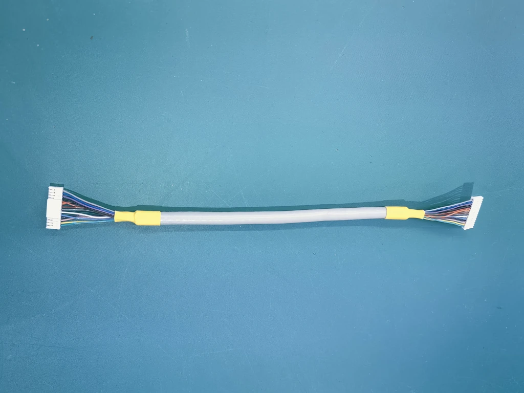
Shielded cable assembly is a custom cable build where foil, braid, drain wire, connector shell contact, cable exit, bend radius, and electrical test scope must be defined before price is treated as final. We review the noise source, grounding method, cable construction, connector family, labels, and production evidence package before quoting so procurement can compare suppliers on risk, not only unit price.
Application Context
A shielded cable assembly is a cable or harness build that adds conductive shielding around one pair, multiple cores, or the full cable bundle to reduce electromagnetic interference. The shield material is only the starting point — the useful work is defining foil, braid, drain wire, connector shell contact, cable exit, bend radius, and electrical test scope before a generic “shielded cable” price is treated as final, so procurement can compare suppliers on risk instead of unit price alone.
EMI shielding is a noise-control method that only works when the shield path, drain wire, shell bond, and equipment grounding strategy are practical in the real assembly. When the requirement reaches past noise control, the shield decision often pairs with a high-temperature cable assembly where probes and sensors sit near heaters and motors, an LVDS cable assembly when display and imaging signals need impedance and connector fit agreed first, a defined wire harness testing service so shield-continuity acceptance is locked before production, and a box build cable assembly when the shielded harness installs into an enclosure with its own grounding rules.
TL;DR
Applications
Best for OEM programs where noise control, connector release, and repeatable test evidence matter as much as the cable drawing.
Servo, encoder, sensor, VFD-adjacent, RS-485, CAN, and machine-control cable assemblies that route near motors, relays, high-current wiring, or metal enclosures.
Robot arm, EOAT, AMR, AGV, inspection, and machine-vision cables where moving routes and repeated bending affect shield life and connector-exit reliability.
Patient-adjacent device leads, diagnostic equipment, imaging accessories, and instrument cables where signal stability, traceability, and clean labeling matter.
Panel-mount, bulkhead, DIN-rail, and cabinet harnesses that need shield pigtails, ground lugs, terminal labels, and installation-friendly routing.
Shielded sensor and controller cables for machinery, charging systems, agriculture, marine, and off-road equipment exposed to vibration, dust, moisture, and service handling.
Engineering samples, adapter pigtails, breakout leads, and first-article builds used to validate grounding strategy before a production harness release.
Engineering Challenges
A drawing that says "shielded cable" but does not define one-end grounding, two-end grounding, 360-degree backshell contact, drain-wire position, or shield-continuity inspection hides an installation problem. The shield path, drain wire, shell bond, and equipment grounding rule are confirmed before a construction is quoted.
A drain wire gives foil shielding a reliable path to ground, but it can break or shift when the cable bends through an aggressive moving route. Static cabinet cables are separated from robot-axis, drag-chain, servo, and encoder cables before jacket, braid, bend radius, and clamp placement are chosen.
Cable shield termination is where shielding transfers into a connector shell, drain lead, backshell, sleeve, or ground lug — and it can fail when overmold pressure, heat-shrink stack-up, or boot geometry disturbs the shield. The mechanical exit is reviewed before tooling or sample approval.
Beyond 100% continuity, shorts, polarity, label, and visual inspection, shielded programs may add shield continuity, shell-to-drain checks, and pull-force in-house (insulation resistance and sample-level functional checks via a qualified third party). The extra inspection steps are matched to the application risk and recorded before release.
Technical Capabilities
Shield constructions, cable and connector formats, grounding methods, environment review, testing, and quality references for a shielded cable assembly program.
Manufacturing Process
Quality & Testing
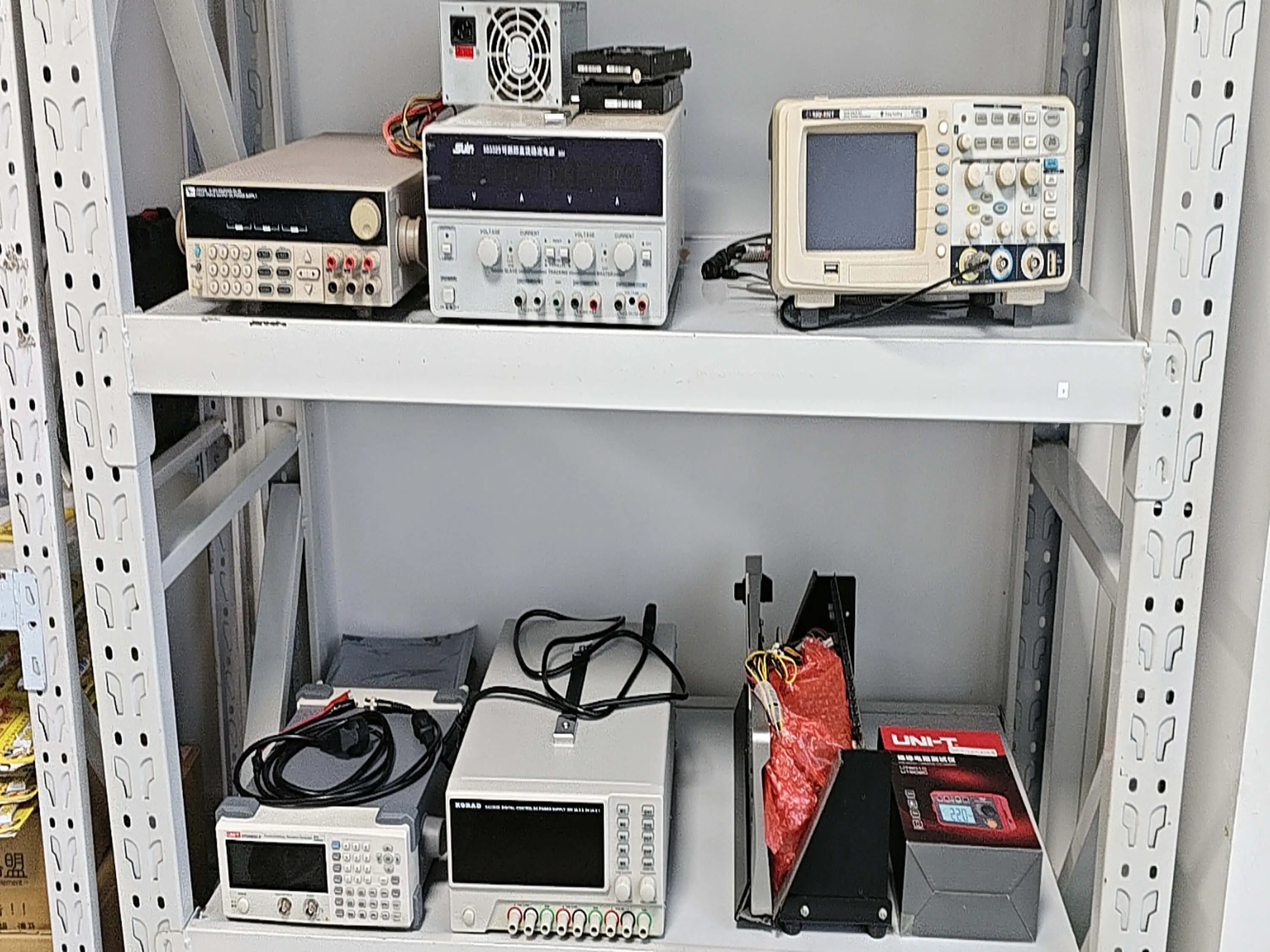
Factory release starts with 100% continuity, shorts, polarity, label, and visual inspection. For shielded programs we add shield continuity, shell-to-drain checks, pull-force, and post-mold electrical test in-house (insulation resistance and sample-level functional checks via a qualified third party) when the application risk justifies the step — with records retained for lot-level traceability before shipment.
Why WHP
A shielded cable supplier should protect the grounding decision, connector release, and production test record before cost is locked.
We ask where the cable routes, which equipment creates noise, whether the shield bonds at one end or both ends, and what the receiving device expects. That prevents a generic shielded cable quote from hiding an installation problem.
A fully braided cable can be harder to route and more expensive than foil plus drain wire. A short cabinet jumper may need clean grounding more than heavy shielding. We separate noise risk, flexibility, connector clamp fit, and inspection cost before recommending a construction.
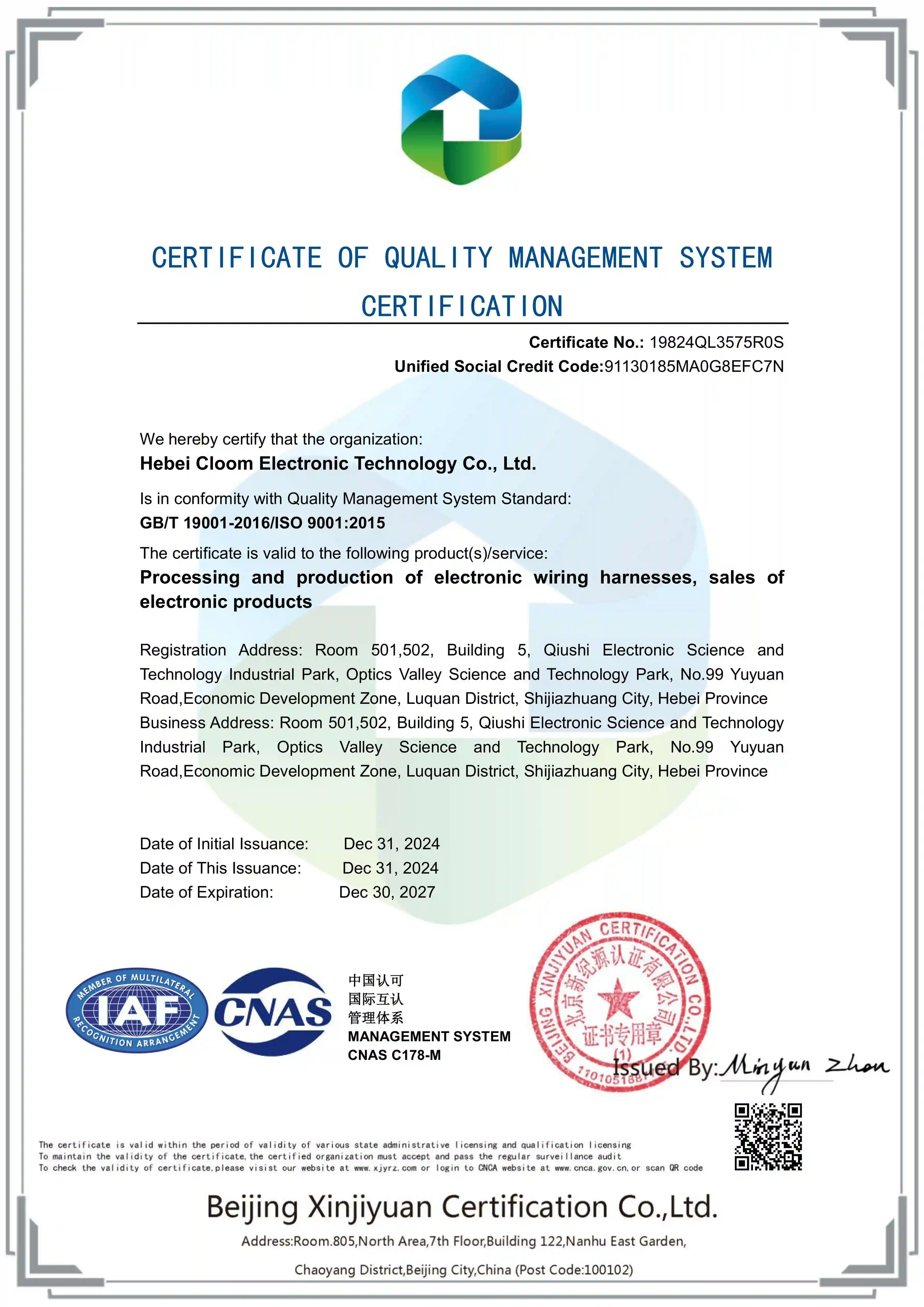
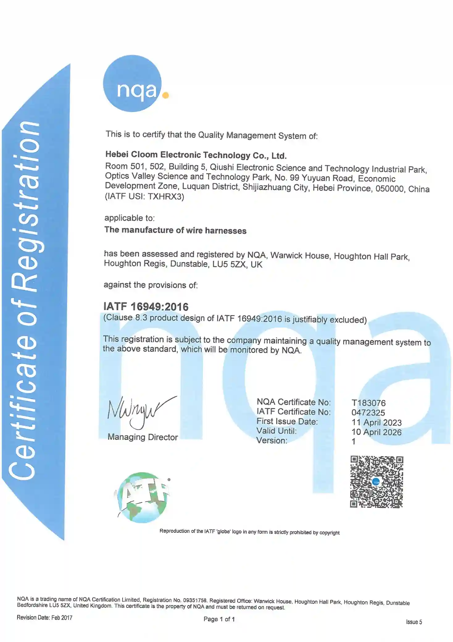
A robotics and automation company needed build-to-print shielded cable assemblies with multiple connector families. China headquarters (Hebei Cloom) holds ISO 9001 and IATF 16949; workmanship and test evidence follow the customer plan. Representative project type shown for illustration.
The approved drawing revision, cable construction, shield method, connector datasheets, label rule, and 100% electrical test plan are retained for repeat orders so engineering approval does not drift during purchasing release.
Shielded cable assembly programs combine EMI-control decisions with wire-harness workmanship and document control, referenced so buyers can align terminology during supplier qualification.
FAQ
OEM Program Entry
Send the drawing, connector part numbers, cable construction target, grounding rule, route environment, quantity, and test scope. We will return shield-path feedback, connector-risk notes, MOQ, sample timing, and a production test plan.
Related Capabilities
Use these pages when EMI control overlaps with heat exposure, signal integrity, or test evidence.
Capabilities
For RFQ-stage buyers who need a build-to-print cable supplier that can control shielding decisions before production release.
Shielded cable assembly is a cable or harness build that adds conductive shielding around one pair, multiple cores, or the full cable bundle to reduce electromagnetic interference. We review foil, braid, foil plus braid, coverage percentage, drain wire position, jacket OD, and connector compatibility before sample release.
EMI shielding is a noise-control method that only works when the shield path, drain wire, shell bond, and equipment grounding strategy are practical in the real assembly. We flag RFQs where a drawing says shielded cable but does not define one-end grounding, two-end grounding, 360-degree backshell contact, or shield continuity inspection.
A drain wire is a conductor that gives foil shielding a reliable electrical path to ground, but it can break or shift when the cable bends through an aggressive moving route. We separate static cabinet cables from robot-axis, drag-chain, servo, and encoder cables before choosing jacket, braid, bend radius, and clamp placement.
A shielded sensor cable is a cable assembly that protects low-level analog, pulse, or communication signals from nearby motors, relays, VFDs, and high-current wiring. We build M8, M12, circular, rectangular, board pigtail, panel-mount, and open-end shielded cables when the drawing defines pinout and grounding expectations.
Cable shield termination is the point where shielding transfers into a connector shell, drain lead, backshell, sleeve, or ground lug. That transition can fail when overmold pressure, heat shrink stack-up, or boot geometry disturbs the shield, so we review the mechanical exit before tooling or sample approval.
Factory release normally starts with 100% continuity, shorts, polarity, label, and visual inspection. For shielded programs we add shield continuity, shell-to-drain checks, insulation resistance (by the customer or a qualified third party, not in-house), pull-force, or sample-level functional checks (by the customer or a qualified third party, not in-house) when the application risk justifies the extra inspection step.
Representative Project
Representative project type we handle, shown for illustration. Not a specific named customer.
A robotics and automation company required custom cable assemblies integrating multiple premium connector brands for advanced automation systems while maintaining quality evidence for high-reliability robotic applications.
We consolidated sourcing and assembly for JST, TE, MOLEX, ANDERSON, and SUMITOMO connector families under ISO 9001:2015 and IATF 16949:2016 certified manufacturing processes while following IPC/WHMA-A-620 production standards. The program secured an initial production order and established a baseline for ongoing robotics manufacturing support.
Working Together
Commercial and engineering answers for teams comparing shielded cable assembly suppliers.
References
Shielded cable assembly programs combine EMI-control decisions with cable workmanship controls. Public references help align buyer language before the RFQ is translated into IPC/WHMA-A-620 workmanship, UL-758 wire review, and ISO 9001-style records.
Factory Engineering Review
Senior factory engineers supporting robotics, industrial automation, medical, and mobile-equipment shielded cable RFQs